Service Manual - Slim Tower
Page 6
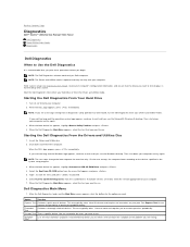
... Main Menu appears, select the test you want to run . Back to Contents Page Diagnostics Dell™ Vostro™ 230s Service Manual-Slim Tower Dell Diagnostics Power Button Light Codes Beep Codes Dell Diagnostics When to Use the Dell Diagnostics It is recommended that you print these procedures before you see the Windows desktop. If you wait too...
... Main Menu appears, select the test you want to run . Back to Contents Page Diagnostics Dell™ Vostro™ 230s Service Manual-Slim Tower Dell Diagnostics Power Button Light Codes Beep Codes Dell Diagnostics When to Use the Dell Diagnostics It is recommended that you print these procedures before you see the Windows desktop. If you wait too...
Service Manual - Slim Tower
Page 9
Back to Contents Page Removing and Replacing Parts Dell™ Vostro™ 230s Service Manual-Slim Tower Cover Chassis Support Bracket Memory Hard Drive Power Button and Card Reader Light Cables Coin-Cell Battery Power Supply Rubber Foot Front Bezel Expansion Card Optical Drive Fan Front I/O Panel and SD Card Reader Heat Sink and Processor System Board Back to Contents Page
Back to Contents Page Removing and Replacing Parts Dell™ Vostro™ 230s Service Manual-Slim Tower Cover Chassis Support Bracket Memory Hard Drive Power Button and Card Reader Light Cables Coin-Cell Battery Power Supply Rubber Foot Front Bezel Expansion Card Optical Drive Fan Front I/O Panel and SD Card Reader Heat Sink and Processor System Board Back to Contents Page

Service Manual - Slim Tower
Page 19
...at www.dell.com/regulatory_compliance. Remove the hard drive. 6. Disconnect all the cables from their routing clips on the chassis. 10. Remove the screws that shipped with your computer, read the safety information that secure the I/O panel to the computer. 11. Remove the power button and ...to install Adobe® Flash® Player from the chassis. 12. Back to Contents Page Front I/O Panel and SD Card Reader Dell™ Vostro™ 230s Service Manual-Slim Tower WARNING: Before working inside your computer. Replacing the Front I/O Panel and SD Card Reader To replace the front ...
...at www.dell.com/regulatory_compliance. Remove the hard drive. 6. Disconnect all the cables from their routing clips on the chassis. 10. Remove the screws that shipped with your computer, read the safety information that secure the I/O panel to the computer. 11. Remove the power button and ...to install Adobe® Flash® Player from the chassis. 12. Back to Contents Page Front I/O Panel and SD Card Reader Dell™ Vostro™ 230s Service Manual-Slim Tower WARNING: Before working inside your computer. Replacing the Front I/O Panel and SD Card Reader To replace the front ...
Service Manual - Slim Tower
Page 24
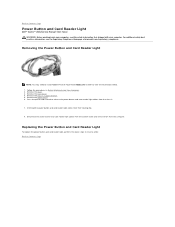
... NOTE: You may need to view the illustrations below. 1. Remove the chassis support bracket. 5. Remove the optical drive. 6. Back to Contents Page Power Button and Card Reader Light Dell™ Vostro™ 230s Service Manual-Slim Tower WARNING: Before working inside your computer, read the safety information that shipped with your computer. Follow the procedures...
... NOTE: You may need to view the illustrations below. 1. Remove the chassis support bracket. 5. Remove the optical drive. 6. Back to Contents Page Power Button and Card Reader Light Dell™ Vostro™ 230s Service Manual-Slim Tower WARNING: Before working inside your computer, read the safety information that shipped with your computer. Follow the procedures...

Service Manual - Slim Tower
Page 28
... Layout Dell™ Vostro™ 230s Service Manual-Slim Tower 1 Power connector (PWR1) 2 Processor heat sink/fan assembly power (CPUFAN1) 3 Memory module connectors (2) 4 Main power connector 5 Battery socket 6 Serial ATA drive connector (SATA3) 7 Serial ATA drive connector (SATA2) 8 Serial ATA drive connector (SATA0) 9 Serial ATA drive connector (SATA1) 10 Chassis fan connector 2(SYS FAN2) 11 Power button & LED...
... Layout Dell™ Vostro™ 230s Service Manual-Slim Tower 1 Power connector (PWR1) 2 Processor heat sink/fan assembly power (CPUFAN1) 3 Memory module connectors (2) 4 Main power connector 5 Battery socket 6 Serial ATA drive connector (SATA3) 7 Serial ATA drive connector (SATA2) 8 Serial ATA drive connector (SATA0) 9 Serial ATA drive connector (SATA1) 10 Chassis fan connector 2(SYS FAN2) 11 Power button & LED...

Service Manual - Slim Tower
Page 29
... your computer. Remove the cover (see the Regulatory Compliance Homepage at the back of cable, press in on Your Computer Dell™ Vostro™ 230s Service Manual-Slim Tower Before Working Inside Your Computer Recommended Tools Turning Off Your Computer After Working Inside Your Computer Before Working...CAUTION: To avoid losing data, save and close all open programs before you are correctly oriented and aligned. Press and hold the power button while the system is not covered by the online or telephone service and support team. Unless otherwise noted, each procedure included in...
... your computer. Remove the cover (see the Regulatory Compliance Homepage at the back of cable, press in on Your Computer Dell™ Vostro™ 230s Service Manual-Slim Tower Before Working Inside Your Computer Recommended Tools Turning Off Your Computer After Working Inside Your Computer Before Working...CAUTION: To avoid losing data, save and close all open programs before you are correctly oriented and aligned. Press and hold the power button while the system is not covered by the online or telephone service and support team. Unless otherwise noted, each procedure included in...

Setup and Features Information Tech Sheet
Page 1
... - Mini Tower - Dell™ Vostro™ 230 Setup and Features Information About Warnings WARNING: A WARNING indicates a potential for property damage, personal injury, or death. WARNING: Do not attempt to service the computer yourself. Front and Back View 1 9 2 8 3 10 7 4 11 6 5 12 1 optical drive 2 optical drive eject button 3 optical drive bay 4 USB 2.0 connectors (2) 5 power button 6 microphone connector 7 headphone...
... - Mini Tower - Dell™ Vostro™ 230 Setup and Features Information About Warnings WARNING: A WARNING indicates a potential for property damage, personal injury, or death. WARNING: Do not attempt to service the computer yourself. Front and Back View 1 9 2 8 3 10 7 4 11 6 5 12 1 optical drive 2 optical drive eject button 3 optical drive bay 4 USB 2.0 connectors (2) 5 power button 6 microphone connector 7 headphone...


