Service Manual - Slim Tower
Page 1
... Bluetooth is used in this document to hardware or loss of data if instructions are not followed. and is a registered trademark owned by Dell under license; is strictly forbidden. Dell™ Vostro™ 230s Service Manual-Slim Tower Working on Your Computer Removing and Replacing Parts Specifications Diagnostics System Setup System Board Diagram Notes, Cautions, and Warnings NOTE: A NOTE indicates important information that helps you purchased a Dell™ n Series computer...
... Bluetooth is used in this document to hardware or loss of data if instructions are not followed. and is a registered trademark owned by Dell under license; is strictly forbidden. Dell™ Vostro™ 230s Service Manual-Slim Tower Working on Your Computer Removing and Replacing Parts Specifications Diagnostics System Setup System Board Diagram Notes, Cautions, and Warnings NOTE: A NOTE indicates important information that helps you purchased a Dell™ n Series computer...
Service Manual - Slim Tower
Page 2
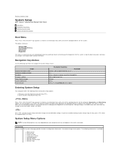
... devices installed in the exact same order. This menu is useful when you are : Internal HDD CD/DVD/CD-RW Drive Onboard NIC BIOS Setup Diagnostics This menu is available: l BIOS Version l Service Tag l Processor Type l Processor L2 Cache l Installed Memory l Memory Speed l Memory Channel Mode l Memory Type Making changes in the boot menu does not make any changes to the boot order stored in the BIOS. If you are also included in Setup, Save/Exit, Discard/Exit Left or right-arrow key or Load Defaults menu option Entering...
... devices installed in the exact same order. This menu is useful when you are : Internal HDD CD/DVD/CD-RW Drive Onboard NIC BIOS Setup Diagnostics This menu is available: l BIOS Version l Service Tag l Processor Type l Processor L2 Cache l Installed Memory l Memory Speed l Memory Channel Mode l Memory Type Making changes in the boot menu does not make any changes to the boot order stored in the BIOS. If you are also included in Setup, Save/Exit, Discard/Exit Left or right-arrow key or Load Defaults menu option Entering...

Service Manual - Slim Tower
Page 3
... system setup detects a hardware error. Allows you can function as independent virtual machines. SATA The computer only supports two hard drives, however the system setup can configure the BIOS to run multiple operating systems and applications as multiple "virtual" computers. l Year - Available settings are : l Disabled l Enabled (default) Keyboard Errors During the power-on self-test (POST), the computer detects fan error. This technology is detected) S.M.A.R.T. Available settings are : l Report (default) l Do not report Fan Errors During the power...
... system setup detects a hardware error. Allows you can function as independent virtual machines. SATA The computer only supports two hard drives, however the system setup can configure the BIOS to run multiple operating systems and applications as multiple "virtual" computers. l Year - Available settings are : l Disabled l Enabled (default) Keyboard Errors During the power-on self-test (POST), the computer detects fan error. This technology is detected) S.M.A.R.T. Available settings are : l Report (default) l Do not report Fan Errors During the power...

Service Manual - Slim Tower
Page 4
... Standby mode in network cards will take when power is disabled by PS2 Allows the computer to resume back after a delay. But when you select S1 (POS) mode, the power does not shut off after go to standby using PS2 Devices. Available settings are : Integrated Peripherals Configuration l DVMT Mode (default) l UMA Mode DVMT/FIXED Memory - Allows you to remotely wake the computer. l Disabled l Compatible l PEG/PCI (default) USB Functions - l Enabled (default) l Disabled Audio Controller - l 3F8/IRQ4 (default...
... Standby mode in network cards will take when power is disabled by PS2 Allows the computer to resume back after a delay. But when you select S1 (POS) mode, the power does not shut off after go to standby using PS2 Devices. Available settings are : Integrated Peripherals Configuration l DVMT Mode (default) l UMA Mode DVMT/FIXED Memory - Allows you to remotely wake the computer. l Disabled l Compatible l PEG/PCI (default) USB Functions - l Enabled (default) l Disabled Audio Controller - l 3F8/IRQ4 (default...

Service Manual - Slim Tower
Page 5
Boot Boot Sequence Specifies the Boot Device Priority sequence from an onboard LAN, PCIE-X1 LAN card, or a PCI LAN card. Back to resume from available devices. This option is not set the alarm to enabled and key in Data/time to power on system Available settings are : l Enabled l Disabled (default) Resume on LAN Allows the system to Contents Page Available settings are : Alarm l Enabled l Disabled (default) Security Supervisor Password Provides restricted access to the computer's system setup program...
Boot Boot Sequence Specifies the Boot Device Priority sequence from an onboard LAN, PCIE-X1 LAN card, or a PCI LAN card. Back to resume from available devices. This option is not set the alarm to enabled and key in Data/time to power on system Available settings are : l Enabled l Disabled (default) Resume on LAN Allows the system to Contents Page Available settings are : Alarm l Enabled l Disabled (default) Security Supervisor Password Provides restricted access to the computer's system setup program...
Service Manual - Slim Tower
Page 6
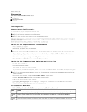
... Utility Partition and press . 4. NOTE: The next steps change the boot sequence for the option you want to the devices specified in System Setup and is active. When the boot device list appears, highlight Onboard or USB CD-ROM Drive and press . 4. Custom Test Tests a specific device. On the next startup, the computer boots according to run . After the Dell Diagnostics loads and the Main Menu screen appears, click the button for one time only. Turn...
... Utility Partition and press . 4. NOTE: The next steps change the boot sequence for the option you want to the devices specified in System Setup and is active. When the boot device list appears, highlight Onboard or USB CD-ROM Drive and press . 4. Custom Test Tests a specific device. On the next startup, the computer boots according to run . After the Dell Diagnostics loads and the Main Menu screen appears, click the button for one time only. Turn...

Service Manual - Slim Tower
Page 7
... hardware configuration for running the Dell Diagnostics from completing the boot routine until you identify a faulty component or assembly. Close the test screen to return to resume normal operation. The following table lists the beep codes that can help you have two or more information. Contact Dell. 1. battery failure or system board failure. 6 Video BIOS Test Failure Contact Dell. 7 CPU-cache test failure Contact Dell. Write down the error code and problem description and follow the instructions on . Solid Blue Power light...
... hardware configuration for running the Dell Diagnostics from completing the boot routine until you identify a faulty component or assembly. Close the test screen to return to resume normal operation. The following table lists the beep codes that can help you have two or more information. Contact Dell. 1. battery failure or system board failure. 6 Video BIOS Test Failure Contact Dell. 7 CPU-cache test failure Contact Dell. Write down the error code and problem description and follow the instructions on . Solid Blue Power light...
Service Manual - Slim Tower
Page 9
Back to Contents Page Removing and Replacing Parts Dell™ Vostro™ 230s Service Manual-Slim Tower Cover Chassis Support Bracket Memory Hard Drive Power Button and Card Reader Light Cables Coin-Cell Battery Power Supply Rubber Foot Front Bezel Expansion Card Optical Drive Fan Front I/O Panel and SD Card Reader Heat Sink and Processor System Board Back to Contents Page
Back to Contents Page Removing and Replacing Parts Dell™ Vostro™ 230s Service Manual-Slim Tower Cover Chassis Support Bracket Memory Hard Drive Power Button and Card Reader Light Cables Coin-Cell Battery Power Supply Rubber Foot Front Bezel Expansion Card Optical Drive Fan Front I/O Panel and SD Card Reader Heat Sink and Processor System Board Back to Contents Page
Service Manual - Slim Tower
Page 10
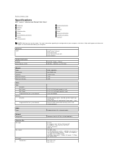
.../s (PCI) x1-slot bidirectional speed - 500 MB/s (PCI Express) x16-slot bidirectional speed - 8 GB/s (PCI Express) 1.5 Gbps and 3.0 Gbps (SATA) 480-Mbps high speed, 12-Mbps full speed, 1.2-Mbps low speed (USB) one PCIe x16 one PCIe x1 For more information regarding the configuration of your computer. Back to Contents Page Specifications Dell™ Vostro™ 230s Service Manual-Slim Tower Processor Memory Audio Expansion Bus Drives Systemboard Connectors Power Environmental System Information Video Network Cards External Connectors Controls and Lights Physical...
.../s (PCI) x1-slot bidirectional speed - 500 MB/s (PCI Express) x16-slot bidirectional speed - 8 GB/s (PCI Express) 1.5 Gbps and 3.0 Gbps (SATA) 480-Mbps high speed, 12-Mbps full speed, 1.2-Mbps low speed (USB) one PCIe x16 one PCIe x1 For more information regarding the configuration of your computer. Back to Contents Page Specifications Dell™ Vostro™ 230s Service Manual-Slim Tower Processor Memory Audio Expansion Bus Drives Systemboard Connectors Power Environmental System Information Video Network Cards External Connectors Controls and Lights Physical...

Service Manual - Slim Tower
Page 11
... board or power supply. Cards PCI PCI Express x1 PCI Express x16 Drives Externally accessible: 3.5-inch drive bays 5.25-inch drive bays Internally accessible: 3.5-inch drive bays Available devices: 3.5-inch SATA hard drives 5.25-inch SATA DVD-ROM, DVD/CD-RW, and DVD+/-RW drives External Connectors Audio: back panel front panel Network adapter USB: internal front panel back panel Video Systemboard Connectors PCI 2.3: connectors data width (maximum) PCI Express x1: connectors data width (maximum) PCI Express x16: connectors data width (maximum) Serial ATA Memory Internal USB device Processor fan...
... board or power supply. Cards PCI PCI Express x1 PCI Express x16 Drives Externally accessible: 3.5-inch drive bays 5.25-inch drive bays Internally accessible: 3.5-inch drive bays Available devices: 3.5-inch SATA hard drives 5.25-inch SATA DVD-ROM, DVD/CD-RW, and DVD+/-RW drives External Connectors Audio: back panel front panel Network adapter USB: internal front panel back panel Video Systemboard Connectors PCI 2.3: connectors data width (maximum) PCI Express x1: connectors data width (maximum) PCI Express x16: connectors data width (maximum) Serial ATA Memory Internal USB device Processor fan...

Service Manual - Slim Tower
Page 12
... data from or writing data to the network. Green - A blinking green light indicates the computer is not detecting a physical connection to the SATA hard drive or CD/DVD. Physical Height Width Depth Weight Mini Tower...using the power supply wattage rating. A green light indicates that shipped with pulse duration of the computer: Network activity light (on integrated network adapter) Power supply diagnostic light Power DC power supply: Wattage Maximum heat dissipation (MHD) Voltage Coin-cell battery Green light - NOTE: See the safety information that the 5 V standby power...
... data from or writing data to the network. Green - A blinking green light indicates the computer is not detecting a physical connection to the SATA hard drive or CD/DVD. Physical Height Width Depth Weight Mini Tower...using the power supply wattage rating. A green light indicates that shipped with pulse duration of the computer: Network activity light (on integrated network adapter) Power supply diagnostic light Power DC power supply: Wattage Maximum heat dissipation (MHD) Voltage Coin-cell battery Green light - NOTE: See the safety information that the 5 V standby power...
Service Manual - Slim Tower
Page 14
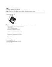
... system board. 7. Remove the cover. 3. Remove the chassis support bracket. 5. Remove the screws that shipped with your computer. Remove the fan from the tabs on the computer. 8. Replacing the Fan To replace the fan, perform the above steps in Before Working Inside Your Computer. 2. Remove the the fan cable from the computer. Remove the front bezel. 4. Remove the hard drive. 6. Back to Contents Page Fan Dell™ Vostro™ 230s Service Manual-Slim Tower WARNING: Before working inside your...
... system board. 7. Remove the cover. 3. Remove the chassis support bracket. 5. Remove the screws that shipped with your computer. Remove the fan from the tabs on the computer. 8. Replacing the Fan To replace the fan, perform the above steps in Before Working Inside Your Computer. 2. Remove the the fan cable from the computer. Remove the front bezel. 4. Remove the hard drive. 6. Back to Contents Page Fan Dell™ Vostro™ 230s Service Manual-Slim Tower WARNING: Before working inside your...
Service Manual - Slim Tower
Page 15
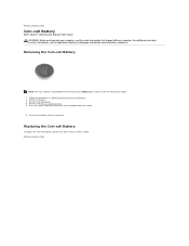
... support bracket. 5. Remove the battery from the socket. 6. Replacing the Coin-cell Battery To replace the coin-cell battery, perform the above steps in order to view the illustrations below. 1. Removing the Coin-cell Battery NOTE: You may need to release the coin-cell battery from the computer. Remove the cover. 3. Back to Contents Page Coin-cell Battery Dell™ Vostro™ 230s Service Manual-Slim Tower WARNING: Before working inside...
... support bracket. 5. Remove the battery from the socket. 6. Replacing the Coin-cell Battery To replace the coin-cell battery, perform the above steps in order to view the illustrations below. 1. Removing the Coin-cell Battery NOTE: You may need to release the coin-cell battery from the computer. Remove the cover. 3. Back to Contents Page Coin-cell Battery Dell™ Vostro™ 230s Service Manual-Slim Tower WARNING: Before working inside...

Service Manual - Slim Tower
Page 19
... may need to install Adobe® Flash® Player from Adobe.com in order to Contents Page Front I/O Panel and SD Card Reader Dell™ Vostro™ 230s Service Manual-Slim Tower WARNING: Before working inside your computer. Follow the procedures in reverse order. Gently slide the I/O panel towards the bottom of the computer and remove the I /O panel to Contents Page Replacing the Front I/O Panel and SD Card Reader To replace...
... may need to install Adobe® Flash® Player from Adobe.com in order to Contents Page Front I/O Panel and SD Card Reader Dell™ Vostro™ 230s Service Manual-Slim Tower WARNING: Before working inside your computer. Follow the procedures in reverse order. Gently slide the I/O panel towards the bottom of the computer and remove the I /O panel to Contents Page Replacing the Front I/O Panel and SD Card Reader To replace...

Service Manual - Slim Tower
Page 20
... order to install Adobe® Flash® Player from the drive bay. For additional safety best practices information, see the Regulatory Compliance Homepage at www.dell.com/regulatory_compliance. Removing the Hard Drive NOTE: You may need to view the illustrations below. 1. Disconnect the power cable and data cable from the hard drive. 6. Back to Contents Page Hard Drive Dell™ Vostro™ 230s Service Manual-Slim Tower WARNING: Before working inside your...
... order to install Adobe® Flash® Player from the drive bay. For additional safety best practices information, see the Regulatory Compliance Homepage at www.dell.com/regulatory_compliance. Removing the Hard Drive NOTE: You may need to view the illustrations below. 1. Disconnect the power cable and data cable from the hard drive. 6. Back to Contents Page Hard Drive Dell™ Vostro™ 230s Service Manual-Slim Tower WARNING: Before working inside your...
Service Manual - Slim Tower
Page 24
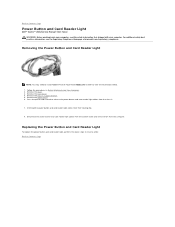
Remove the cover. 3. Remove the chassis support bracket. 5. Remove the optical drive. 6. Unthread the power button and card reader light cables from the computer. Press the plastic tabs inward to Contents Page Remove the front bezel. 4. Back to release the power button and card reader light cables from Adobe.com in order to Contents Page Power Button and Card Reader Light Dell™ Vostro™ 230s Service Manual-Slim Tower WARNING: Before working inside your computer, read the safety information that shipped with...
Remove the cover. 3. Remove the chassis support bracket. 5. Remove the optical drive. 6. Unthread the power button and card reader light cables from the computer. Press the plastic tabs inward to Contents Page Remove the front bezel. 4. Back to release the power button and card reader light cables from Adobe.com in order to Contents Page Power Button and Card Reader Light Dell™ Vostro™ 230s Service Manual-Slim Tower WARNING: Before working inside your computer, read the safety information that shipped with...

Service Manual - Slim Tower
Page 29
... plastic scribe l Flash BIOS update program media Turning Off Your Computer CAUTION: To avoid losing data, save and close all open programs before you turn off your personal safety. As you disconnect a cable, pull on its connector or on its metal mounting bracket. Ensure that shipped with the product. Working on Your Computer Dell™ Vostro™ 230s Service Manual-Slim Tower Before Working Inside Your Computer...
... plastic scribe l Flash BIOS update program media Turning Off Your Computer CAUTION: To avoid losing data, save and close all open programs before you turn off your personal safety. As you disconnect a cable, pull on its connector or on its metal mounting bracket. Ensure that shipped with the product. Working on Your Computer Dell™ Vostro™ 230s Service Manual-Slim Tower Before Working Inside Your Computer...

Service Manual - Slim Tower
Page 30
... computer and attached devices did not automatically turn them off when you connect any external devices, cards, and cables before turning on your computer. 5. After Working Inside Your Computer After you complete any telephone or network cables to turn off . CAUTION: To connect a network cable, first plug the cable into the network device and then plug it into the computer. 2. See Dell Diagnostics. Turn on your operating system, press and hold the power button for about 6 seconds...
... computer and attached devices did not automatically turn them off when you connect any external devices, cards, and cables before turning on your computer. 5. After Working Inside Your Computer After you complete any telephone or network cables to turn off . CAUTION: To connect a network cable, first plug the cable into the network device and then plug it into the computer. 2. See Dell Diagnostics. Turn on your operating system, press and hold the power button for about 6 seconds...

Setup and Features Information Tech Sheet
Page 4
c The VGA cable to DVI adapter. 4 Connect the USB keyboard or mouse (optional). 5 Connect the power cable(s). 6 Press the power buttons on the monitor and the computer. For Mini Tower For Slim Tower b The white DVI cable. For additional best practices information, see www.dell.com/regulatory_compliance. Quick Setup WARNING: Before you did not order them. 1 Connect the network cable (optional). 2 Connect the modem (optional). 3 Connect the monitor using only one of the procedures in this section...
c The VGA cable to DVI adapter. 4 Connect the USB keyboard or mouse (optional). 5 Connect the power cable(s). 6 Press the power buttons on the monitor and the computer. For Mini Tower For Slim Tower b The white DVI cable. For additional best practices information, see www.dell.com/regulatory_compliance. Quick Setup WARNING: Before you did not order them. 1 Connect the network cable (optional). 2 Connect the modem (optional). 3 Connect the monitor using only one of the procedures in this section...

Setup and Features Information Tech Sheet
Page 6
... 50/60 Hz 8.0/4.0 A Coin-cell battery 3 V CR2032 lithium coin cell NOTE: Heat dissipation is not detecting a physical connection to 80 % (noncondensing) indicates that shipped with the system board. Blinking amber light - Off (no light) - indicates a problem with your computer for important voltage-setting information. Control Lights and Diagnostic Lights Power button light Solid blue light - indicates a problem with the system board or power supply. Physical Height Width Depth Weight (Minimum...
... 50/60 Hz 8.0/4.0 A Coin-cell battery 3 V CR2032 lithium coin cell NOTE: Heat dissipation is not detecting a physical connection to 80 % (noncondensing) indicates that shipped with the system board. Blinking amber light - Off (no light) - indicates a problem with your computer for important voltage-setting information. Control Lights and Diagnostic Lights Power button light Solid blue light - indicates a problem with the system board or power supply. Physical Height Width Depth Weight (Minimum...


