Setup and Quick Reference Guide
Page 10
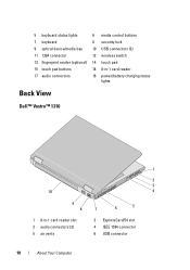
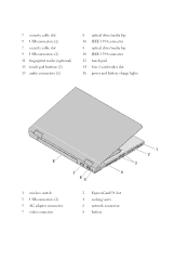
5 keyboard status lights 6 media control buttons 7 keyboard 8 security lock 9 optical device/media bay 10 USB connectors (2) 11 1394 connector 12 wireless switch 13 fingerprint reader (optional) 14 touch pad 15 touch pad buttons 16 8-in-1 card reader 17 audio connectors 18 power/battery charging status lights Back View Dell™ Vostro™ 1310 1 2 3 10 4 9 8 7 6 5 1 8-in-1 card reader slot 3 audio connectors (2) 5 air vents 2 ExpressCard/54 slot 4 IEEE 1394 connector 6 USB connector 10 About Your Computer
5 keyboard status lights 6 media control buttons 7 keyboard 8 security lock 9 optical device/media bay 10 USB connectors (2) 11 1394 connector 12 wireless switch 13 fingerprint reader (optional) 14 touch pad 15 touch pad buttons 16 8-in-1 card reader 17 audio connectors 18 power/battery charging status lights Back View Dell™ Vostro™ 1310 1 2 3 10 4 9 8 7 6 5 1 8-in-1 card reader slot 3 audio connectors (2) 5 air vents 2 ExpressCard/54 slot 4 IEEE 1394 connector 6 USB connector 10 About Your Computer

Setup and Quick Reference Guide
Page 17
.... If you are using a DSL or cable/satellite modem connection, contact your ISP or cellular phone service for more information. 4 5 1 1 Internet service 3 wireless router 3 2 5 laptop computer with wireless network card 3 2 1 2 cable or DSL modem 4 laptop computer with network adapter Connecting to the Internet To connect to the Internet, you set up connection, connect...
.... If you are using a DSL or cable/satellite modem connection, contact your ISP or cellular phone service for more information. 4 5 1 1 Internet service 3 wireless router 3 2 5 laptop computer with wireless network card 3 2 1 2 cable or DSL modem 4 laptop computer with network adapter Connecting to the Internet To connect to the Internet, you set up connection, connect...
Setup and Quick Reference Guide
Page 25
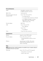
... upgrades are available for PCI-e Mini-Card WLAN and card with Bluetooth® wireless technology (Dell™ Wireless 360) RJ-45 port Vostro 1310 and 1510: • four USB ports Vostro 1710: • six USB ports 15-pin VGA video connector Communications Modem Network adapter Wireless supports external USB modem Vostro 1310, 1510, and 1710: • 10/100/1000 Ethernet LAN...
... upgrades are available for PCI-e Mini-Card WLAN and card with Bluetooth® wireless technology (Dell™ Wireless 360) RJ-45 port Vostro 1310 and 1510: • four USB ports Vostro 1710: • six USB ports 15-pin VGA video connector Communications Modem Network adapter Wireless supports external USB modem Vostro 1310, 1510, and 1710: • 10/100/1000 Ethernet LAN...
Setup and Features Information Tech Sheet
Page 2
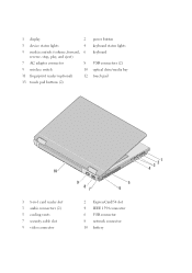
1 display 2 3 device status lights 4 5 media controls (volume, forward, 6 reverse, stop, play, and eject) 7 AC adapter connector 8 9 wireless switch 10 11 fingerprint reader (optional) 12 13 touch pad buttons (2) power button keyboard status lights keyboard USB connectors (2) optical drive/media bay touch pad 10 1 8-in-1 card reader slot 3 audio connectors (2) 5 cooling vents 7 security cable slot 9 video connector 9 87 5 6 2 ExpressCard/54 slot 4 IEEE 1394 connector 6 USB connector 8 network connector 10 battery 3 21 4
1 display 2 3 device status lights 4 5 media controls (volume, forward, 6 reverse, stop, play, and eject) 7 AC adapter connector 8 9 wireless switch 10 11 fingerprint reader (optional) 12 13 touch pad buttons (2) power button keyboard status lights keyboard USB connectors (2) optical drive/media bay touch pad 10 1 8-in-1 card reader slot 3 audio connectors (2) 5 cooling vents 7 security cable slot 9 video connector 9 87 5 6 2 ExpressCard/54 slot 4 IEEE 1394 connector 6 USB connector 8 network connector 10 battery 3 21 4
Setup and Features Information Tech Sheet
Page 4
7 security cable slot 9 USB connectors (2) 7 security cable slot 9 USB connectors (2) 11 fingerprint reader (optional) 13 touch pad buttons (2) 15 audio connectors (2) 8 optical drive/media bay 10 IEEE 1394 connector 8 optical drive/media bay 10 IEEE 1394 connector 12 touch pad 14 8-in-1 card reader slot 16 power and battery charge lights 8 7 4 65 1 wireless switch 3 USB connectors (2) 5 AC adapter connector 7 video connector 2 ExpressCard/54 slot 4 cooling vents 6 network connector 8 battery 1 2 3
7 security cable slot 9 USB connectors (2) 7 security cable slot 9 USB connectors (2) 11 fingerprint reader (optional) 13 touch pad buttons (2) 15 audio connectors (2) 8 optical drive/media bay 10 IEEE 1394 connector 8 optical drive/media bay 10 IEEE 1394 connector 12 touch pad 14 8-in-1 card reader slot 16 power and battery charge lights 8 7 4 65 1 wireless switch 3 USB connectors (2) 5 AC adapter connector 7 video connector 2 ExpressCard/54 slot 4 cooling vents 6 network connector 8 battery 1 2 3
Setup and Features Information Tech Sheet
Page 5
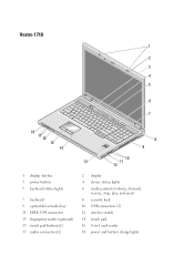
Vostro 1710 1 2 3 4 5 6 9 7 A 18 17 16 15 14 8 9 10 13 11 12 1 display latches 3 power button 5 keyboard status lights 7 keyboard 9 optical drive/media bay 11 IEEE 1394 connector 13 fingerprint reader (optional) 15 touch pad buttons(2) 17 audio connectors(2) 2 display 4 device status lights 6 media controls (volume, forward, reverse, stop, play, and eject) 8 security lock 10 USB connectors (2) 12 wireless switch 14 touch pad 16 8-in-1 card reader 18 power and battery charge lights
Vostro 1710 1 2 3 4 5 6 9 7 A 18 17 16 15 14 8 9 10 13 11 12 1 display latches 3 power button 5 keyboard status lights 7 keyboard 9 optical drive/media bay 11 IEEE 1394 connector 13 fingerprint reader (optional) 15 touch pad buttons(2) 17 audio connectors(2) 2 display 4 device status lights 6 media controls (volume, forward, reverse, stop, play, and eject) 8 security lock 10 USB connectors (2) 12 wireless switch 14 touch pad 16 8-in-1 card reader 18 power and battery charge lights

Service Manual
Page 1
... in this document to refer to either potential damage to hardware or loss of your computer. A01 Dell™ Vostro™ 1710 Service Manual Troubleshooting Before Working on Your Computer Hard Drive Wireless Local Area Network (WLAN) Card Fan Processor Thermal-Cooling Assembly Processor Module Memory Hinge Cover Keyboard Power Button and Multimedia Button Pads...
... in this document to refer to either potential damage to hardware or loss of your computer. A01 Dell™ Vostro™ 1710 Service Manual Troubleshooting Before Working on Your Computer Hard Drive Wireless Local Area Network (WLAN) Card Fan Processor Thermal-Cooling Assembly Processor Module Memory Hinge Cover Keyboard Power Button and Multimedia Button Pads...
Service Manual
Page 6
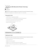
... Hard Drive for an illustration of the hard drive cover. 3. Back to the card. 2. Removing the Card 1. Replace the hard drive cover. Back to Contents Page Internal Card With Bluetooth® Wireless Technology Dell™ Vostro™ 1710 Service Manual Removing the Card Replacing the Card CAUTION: Before you begin any of the procedures in this section, follow the...
... Hard Drive for an illustration of the hard drive cover. 3. Back to the card. 2. Removing the Card 1. Replace the hard drive cover. Back to Contents Page Internal Card With Bluetooth® Wireless Technology Dell™ Vostro™ 1710 Service Manual Removing the Card Replacing the Card CAUTION: Before you begin any of the procedures in this section, follow the...
Service Manual
Page 22
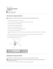
... palm rest upward to Contents Page Fingerprint Reader Dell™ Vostro™ 1710 Service Manual Removing the Fingerprint Reader Replacing the Fingerprint...you begin the following procedure, follow the safety instructions that shipped with Bluetooth® wireless technology are properly routed before snapping the palm rest into place. Back to release...of the hard drive cover. 3. This procedure assumes that shipped with your computer. 1. Remove the WLAN card (see Removing the Hinge Cover). 5. Rotate the retaining bracket on the fingerprint reader connector on Your Computer...
... palm rest upward to Contents Page Fingerprint Reader Dell™ Vostro™ 1710 Service Manual Removing the Fingerprint Reader Replacing the Fingerprint...you begin the following procedure, follow the safety instructions that shipped with Bluetooth® wireless technology are properly routed before snapping the palm rest into place. Back to release...of the hard drive cover. 3. This procedure assumes that shipped with your computer. 1. Remove the WLAN card (see Removing the Hinge Cover). 5. Rotate the retaining bracket on the fingerprint reader connector on Your Computer...
Service Manual
Page 30
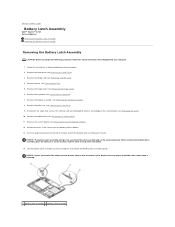
... (see Removing the Hard Drive). 3. NOTICE: Before you begin the following procedure, follow the safety instructions that secures the internal card with your computer. 1. Remove the hard drive (see Removing the Palm Rest). 9. Remove the optical drive (see Removing the ... Drive). 11. Disconnect the cable that shipped with Bluetooth® wireless technology to the system board (see Removing the Card). 10. Back to Contents Page Battery Latch Assembly Dell™ Vostro™ 1710 Service Manual Removing the Battery Latch Assembly Replacing the Battery Latch Assembly...
... (see Removing the Hard Drive). 3. NOTICE: Before you begin the following procedure, follow the safety instructions that secures the internal card with your computer. 1. Remove the hard drive (see Removing the Palm Rest). 9. Remove the optical drive (see Removing the ... Drive). 11. Disconnect the cable that shipped with Bluetooth® wireless technology to the system board (see Removing the Card). 10. Back to Contents Page Battery Latch Assembly Dell™ Vostro™ 1710 Service Manual Removing the Battery Latch Assembly Replacing the Battery Latch Assembly...
Service Manual
Page 31
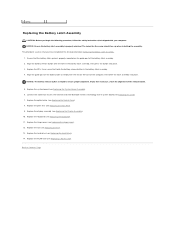
...the safety instructions that you feel resistance, check the alignment of the battery latch assembly. 2. This procedure assumes that shipped with Bluetooth wireless technology to ensure proper alignment. Replace the keyboard (see Replacing the Hinge Cover). 12. Replace the hinge cover (see Replacing the ... Palm Rest). 9. If you have completed the removal procedure Removing the Battery Latch Assembly. 1. Replace the system board (see Replacing the Card). 7. Replace the M2 x 3-mm screw that the battery latch spring is properly oriented. Align the guide post on the base of...
...the safety instructions that you feel resistance, check the alignment of the battery latch assembly. 2. This procedure assumes that shipped with Bluetooth wireless technology to ensure proper alignment. Replace the keyboard (see Replacing the Hinge Cover). 12. Replace the hinge cover (see Replacing the ... Palm Rest). 9. If you have completed the removal procedure Removing the Battery Latch Assembly. 1. Replace the system board (see Replacing the Card). 7. Replace the M2 x 3-mm screw that the battery latch spring is properly oriented. Align the guide post on the base of...
Service Manual
Page 34
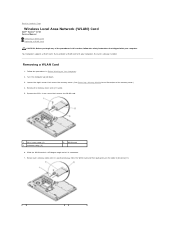
... each antenna cable until it is already installed. Back to Contents Page Wireless Local Area Network (WLAN) Card Dell™ Vostro™ 1710 Service Manual Removing a WLAN Card Replacing a WLAN Card CAUTION: Before you ordered a WLAN card with your computer, the card is positioned away from the WLAN card and then pull gently on Your Computer. 2. If you begin any...
... each antenna cable until it is already installed. Back to Contents Page Wireless Local Area Network (WLAN) Card Dell™ Vostro™ 1710 Service Manual Removing a WLAN Card Replacing a WLAN Card CAUTION: Before you ordered a WLAN card with your computer, the card is positioned away from the WLAN card and then pull gently on Your Computer. 2. If you begin any...
Service Manual
Page 39
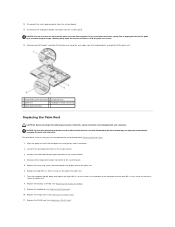
... Align the palm rest with your computer. Replace the display assembly (see Replacing a WLAN Card). 12. Reconnect the finger print reader connector to the system board. 4. Replace the WLAN card (see Replacing the Display Assembly). 9. Disconnect the fingerprint reader connector from the system board. ...removal procedure Removing the Palm Rest. 1. This procedure assumes that the touch pad cable and the cable for the internal card with Bluetooth® wireless technology are properly routed before snapping the palm rest into place. 2. Replace the three cap screws located towards the ...
... Align the palm rest with your computer. Replace the display assembly (see Replacing a WLAN Card). 12. Reconnect the finger print reader connector to the system board. 4. Replace the WLAN card (see Replacing the Display Assembly). 9. Disconnect the fingerprint reader connector from the system board. ...removal procedure Removing the Palm Rest. 1. This procedure assumes that the touch pad cable and the cable for the internal card with Bluetooth® wireless technology are properly routed before snapping the palm rest into place. 2. Replace the three cap screws located towards the ...


