
Setup and Quick Reference Guide
Page 7
About Your Computer Front View Dell™ Vostro™ 1310 13 12 1 display 3 device status lights 1 2 3 4 5 6 9 A 7 8 9 11 10 2 power button 4 keyboard status lights About Your Computer 7
About Your Computer Front View Dell™ Vostro™ 1310 13 12 1 display 3 device status lights 1 2 3 4 5 6 9 A 7 8 9 11 10 2 power button 4 keyboard status lights About Your Computer 7
Setup and Quick Reference Guide
Page 8
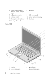
5 media controls (volume, forward, reverse, stop, play, eject) 7 AC adapter connector 9 wireless switch 11 fingerprint reader (optional) 13 touch pad buttons (2) Vostro 1510 6 keyboard 8 USB connectors (2) 10 optical device in media bay 12 touch pad 1 2 3 4 5 6 9 A 16 15 14 13 12 1 display 3 device status lights 8 About Your Computer 7 8 9 11 10 2 power button 4 keyboard status lights
5 media controls (volume, forward, reverse, stop, play, eject) 7 AC adapter connector 9 wireless switch 11 fingerprint reader (optional) 13 touch pad buttons (2) Vostro 1510 6 keyboard 8 USB connectors (2) 10 optical device in media bay 12 touch pad 1 2 3 4 5 6 9 A 16 15 14 13 12 1 display 3 device status lights 8 About Your Computer 7 8 9 11 10 2 power button 4 keyboard status lights
Setup and Quick Reference Guide
Page 9
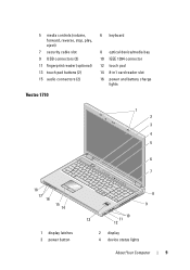
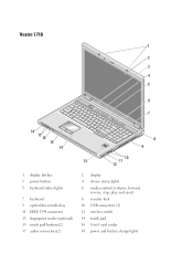
5 media controls (volume, forward, reverse, stop, play, eject) 7 security cable slot 9 USB connectors (2) 11 fingerprint reader (optional) 13 touch pad buttons (2) 15 audio connectors (2) Vostro 1710 6 keyboard 8 optical device/media bay 10 IEEE 1394 connector 12 touch pad 14 8-in1 card reader slot 16 power and battery charge lights 1 2 3 4 5 6 9 7 A 18 17 16 15 14 1 display latches 3 power button 8 9 10 13 11 12 2 display 4 device status lights About Your Computer 9
5 media controls (volume, forward, reverse, stop, play, eject) 7 security cable slot 9 USB connectors (2) 11 fingerprint reader (optional) 13 touch pad buttons (2) 15 audio connectors (2) Vostro 1710 6 keyboard 8 optical device/media bay 10 IEEE 1394 connector 12 touch pad 14 8-in1 card reader slot 16 power and battery charge lights 1 2 3 4 5 6 9 7 A 18 17 16 15 14 1 display latches 3 power button 8 9 10 13 11 12 2 display 4 device status lights About Your Computer 9
Setup and Quick Reference Guide
Page 10
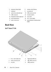
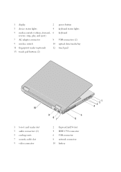
5 keyboard status lights 6 media control buttons 7 keyboard 8 security lock 9 optical device/media bay 10 USB connectors (2) 11 1394 connector 12 wireless switch 13 fingerprint reader (optional) 14 touch pad 15 touch pad buttons 16 8-in-1 card reader 17 audio connectors 18 power/battery charging status lights Back View Dell™ Vostro™ 1310 1 2 3 10 4 9 8 7 6 5 1 8-in-1 card reader slot 3 audio connectors (2) 5 air vents 2 ExpressCard/54 slot 4 IEEE 1394 connector 6 USB connector 10 About Your Computer
5 keyboard status lights 6 media control buttons 7 keyboard 8 security lock 9 optical device/media bay 10 USB connectors (2) 11 1394 connector 12 wireless switch 13 fingerprint reader (optional) 14 touch pad 15 touch pad buttons 16 8-in-1 card reader 17 audio connectors 18 power/battery charging status lights Back View Dell™ Vostro™ 1310 1 2 3 10 4 9 8 7 6 5 1 8-in-1 card reader slot 3 audio connectors (2) 5 air vents 2 ExpressCard/54 slot 4 IEEE 1394 connector 6 USB connector 10 About Your Computer
Setup and Quick Reference Guide
Page 16
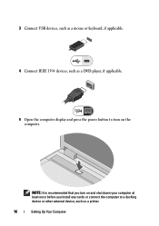
3 Connect USB devices, such as a mouse or keyboard, if applicable. 4 Connect IEEE 1394 devices, such as a DVD player, if applicable. 5 Open the computer display and press the power button to a docking device or other external device, such as a printer. 16 Setting Up Your Computer NOTE: It is recommended that you turn on and shut down your computer at least once before you install any cards or connect the computer to turn on the computer.
3 Connect USB devices, such as a mouse or keyboard, if applicable. 4 Connect IEEE 1394 devices, such as a DVD player, if applicable. 5 Open the computer display and press the power button to a docking device or other external device, such as a printer. 16 Setting Up Your Computer NOTE: It is recommended that you turn on and shut down your computer at least once before you install any cards or connect the computer to turn on the computer.

Setup and Quick Reference Guide
Page 28
...Vostro 1710: • 359.4 mm x 118.9 mm x 5.2 mm (14.15 x 4.681 x 0.205 inches) 28 Specifications Display (continued) WXGA+ anti-glare WXGA+ with TrueLife WSXGA with TrueLife WUXGA with TrueLife Refresh rate Operating angle Horizontal viewing angle Controls Keyboard Number of keys Layout Size: Standard Maximum 1440 x 900 (Vostro 1510 and 1710) 1440 x 900 (Vostro 1510 and 1710...) 1680 x 1050 (Vostro 1510) 1920 x 1200 (Vostro 1510 and 1710) 60 Hz 0&#...
...Vostro 1710: • 359.4 mm x 118.9 mm x 5.2 mm (14.15 x 4.681 x 0.205 inches) 28 Specifications Display (continued) WXGA+ anti-glare WXGA+ with TrueLife WSXGA with TrueLife WUXGA with TrueLife Refresh rate Operating angle Horizontal viewing angle Controls Keyboard Number of keys Layout Size: Standard Maximum 1440 x 900 (Vostro 1510 and 1710) 1440 x 900 (Vostro 1510 and 1710...) 1680 x 1050 (Vostro 1510) 1920 x 1200 (Vostro 1510 and 1710) 60 Hz 0&#...
Setup and Quick Reference Guide
Page 35
... repetitive three short beeps. Beep Codes Your computer might be malfunctioning or incorrectly installed. • If the power light is connected and powered on the keyboard, move the mouse, or press the power button to indicate different states: • If the power light is off, the computer is either turned off...
... repetitive three short beeps. Beep Codes Your computer might be malfunctioning or incorrectly installed. • If the power light is connected and powered on the keyboard, move the mouse, or press the power button to indicate different states: • If the power light is off, the computer is either turned off...
Setup and Quick Reference Guide
Page 39
... F A I L U R E - Run the Keyboard Controller test in the Dell Diagnostics (see "Dell Diagnostics" on page 42). Run the Keyboard Controller test in the Dell Diagnostics (see "Dell Diagnostics" on page 42). The hard drive may be... played. Run the Hard Disk Drive tests in the Dell Diagnostics (see "Dell Diagnostics" on page 42). K E Y B O A R D C O N T R O L L E R F A I L U R E - For external keyboards or keypads, check the cable connection. The message is installed. Troubleshooting 39 D I S K D R I V E R E A D F A ...
... F A I L U R E - Run the Keyboard Controller test in the Dell Diagnostics (see "Dell Diagnostics" on page 42). Run the Keyboard Controller test in the Dell Diagnostics (see "Dell Diagnostics" on page 42). The hard drive may be... played. Run the Hard Disk Drive tests in the Dell Diagnostics (see "Dell Diagnostics" on page 42). K E Y B O A R D C O N T R O L L E R F A I L U R E - For external keyboards or keypads, check the cable connection. The message is installed. Troubleshooting 39 D I S K D R I V E R E A D F A ...

Setup and Quick Reference Guide
Page 42
... may be loose. System configuration settings are corrupted. Correct the settings for more information. Run the System Memory tests and the Keyboard Controller test in Lockups and Software Problems (see "Dell Diagnostics" on the system board may require recharging. D A Y C L O C K L O S T P O W E R - Connect your computer to an electrical outlet to an electrical outlet; The reserve...
... may be loose. System configuration settings are corrupted. Correct the settings for more information. Run the System Memory tests and the Keyboard Controller test in Lockups and Software Problems (see "Dell Diagnostics" on the system board may require recharging. D A Y C L O C K L O S T P O W E R - Connect your computer to an electrical outlet to an electrical outlet; The reserve...
Setup and Quick Reference Guide
Page 45
...might be malfunctioning or incorrectly installed. • Ensure that the processor power cable is connected and powered on, see "Beep Codes" on the keyboard, move the mouse, or press the power button to resume normal operation. The computer is not receiving power. • Reseat the power cable...connected and powered on. • If the display is securely connected to the system board power connector (see your Service Manual at support.dell.com). Power Problems CAUTION: Before you begin any of the computer and the electrical outlet. • Bypass power strips, power extension cables...
...might be malfunctioning or incorrectly installed. • Ensure that the processor power cable is connected and powered on, see "Beep Codes" on the keyboard, move the mouse, or press the power button to resume normal operation. The computer is not receiving power. • Reseat the power cable...connected and powered on. • If the display is securely connected to the system board power connector (see your Service Manual at support.dell.com). Power Problems CAUTION: Before you begin any of the computer and the electrical outlet. • Bypass power strips, power extension cables...
Setup and Quick Reference Guide
Page 46
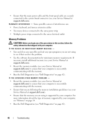
...Memory Problems CAUTION: Before you are following the memory installation guidelines (see your Service Manual at support.dell.com). Some possible causes of interference are: • Power, keyboard, and mouse extension cables • Too many devices connected to the same power strip • ...of memory supported by your computer. • Ensure that your computer is successfully communicating with the memory. • Run the Dell Diagnostics (see "Dell Diagnostics" on page 42). 46 Troubleshooting IF YOU RECEIVE AN INSUFFICIENT MEMORY MESSAGE - • Save and close any open ...
...Memory Problems CAUTION: Before you are following the memory installation guidelines (see your Service Manual at support.dell.com). Some possible causes of interference are: • Power, keyboard, and mouse extension cables • Too many devices connected to the same power strip • ...of memory supported by your computer. • Ensure that your computer is successfully communicating with the memory. • Run the Dell Diagnostics (see "Dell Diagnostics" on page 42). 46 Troubleshooting IF YOU RECEIVE AN INSUFFICIENT MEMORY MESSAGE - • Save and close any open ...
Setup and Quick Reference Guide
Page 47
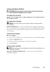
... the program that shipped with your computer. Lockups and Software Problems CAUTION: Before you begin any of the procedures in its documentation or on your keyboard or moving your mouse, press and hold the power button for at least 8 to perform an operating system shutdown.
... the program that shipped with your computer. Lockups and Software Problems CAUTION: Before you begin any of the procedures in its documentation or on your keyboard or moving your mouse, press and hold the power button for at least 8 to perform an operating system shutdown.
Setup and Quick Reference Guide
Page 48
... run the software. See the software documentation for information. • Ensure that the device drivers do not conflict with the operating system installed on your keyboard or moving your mouse, press and hold the power button for an earlier Microsoft® Windows® operating system RUN THE PROGRAM COMPATIBILITY WIZARD - Other...
... run the software. See the software documentation for information. • Ensure that the device drivers do not conflict with the operating system installed on your keyboard or moving your mouse, press and hold the power button for an earlier Microsoft® Windows® operating system RUN THE PROGRAM COMPATIBILITY WIZARD - Other...

Setup and Quick Reference Guide
Page 59
... installation, back up all data files on your configuration, you installed the new device driver. The Dell Factory Image Restore welcome screen appears. 6 Click Next. Reinstalling Software 59 3 Select a keyboard layout and click Next. 4 To access the recovery options, log on page 52. The restore process... begins and may need to the operating state it was in the User name field, then click OK. 5 Click Dell Factory Image Restore. A message appears ...
... installation, back up all data files on your configuration, you installed the new device driver. The Dell Factory Image Restore welcome screen appears. 6 Click Next. Reinstalling Software 59 3 Select a keyboard layout and click Next. 4 To access the recovery options, log on page 52. The restore process... begins and may need to the operating state it was in the User name field, then click OK. 5 Click Dell Factory Image Restore. A message appears ...
Setup and Quick Reference Guide
Page 67
Ensure that the computer documentation is available. Remember to type some commands at the keyboard, relay detailed information during operations, or try other troubleshooting steps possible only at or near the computer. You may also be asked for assistance and... call from a telephone at the computer itself. Getting Help 67 The code helps Dell's automated-support telephone system direct your call . You may be asked to fill out the Diagnostics Checklist (see "Diagnostics Checklist" on page 68). If possible...
Ensure that the computer documentation is available. Remember to type some commands at the keyboard, relay detailed information during operations, or try other troubleshooting steps possible only at or near the computer. You may also be asked for assistance and... call from a telephone at the computer itself. Getting Help 67 The code helps Dell's automated-support telephone system direct your call . You may be asked to fill out the Diagnostics Checklist (see "Diagnostics Checklist" on page 68). If possible...
Setup and Features Information Tech Sheet
Page 2
1 display 2 3 device status lights 4 5 media controls (volume, forward, 6 reverse, stop, play, and eject) 7 AC adapter connector 8 9 wireless switch 10 11 fingerprint reader (optional) 12 13 touch pad buttons (2) power button keyboard status lights keyboard USB connectors (2) optical drive/media bay touch pad 10 1 8-in-1 card reader slot 3 audio connectors (2) 5 cooling vents 7 security cable slot 9 video connector 9 87 5 6 2 ExpressCard/54 slot 4 IEEE 1394 connector 6 USB connector 8 network connector 10 battery 3 21 4
1 display 2 3 device status lights 4 5 media controls (volume, forward, 6 reverse, stop, play, and eject) 7 AC adapter connector 8 9 wireless switch 10 11 fingerprint reader (optional) 12 13 touch pad buttons (2) power button keyboard status lights keyboard USB connectors (2) optical drive/media bay touch pad 10 1 8-in-1 card reader slot 3 audio connectors (2) 5 cooling vents 7 security cable slot 9 video connector 9 87 5 6 2 ExpressCard/54 slot 4 IEEE 1394 connector 6 USB connector 8 network connector 10 battery 3 21 4

Setup and Features Information Tech Sheet
Page 3
The chassis color of Vostro 1510 is Cherry Red. 1 2 3 4 5 6 9 A 16 15 14 13 12 11 9 10 1 display 2 3 device status lights 4 5 media controls (volume, forward, 6 reverse, stop, play, and eject) power button keyboard status lights keyboard 7 8 Vostro 1510/2510 NOTE: The difference between Vostro 1510 and Vostro 2510 is the color of Vostro 2510 is Black and the chassis color of the chassis.
The chassis color of Vostro 1510 is Cherry Red. 1 2 3 4 5 6 9 A 16 15 14 13 12 11 9 10 1 display 2 3 device status lights 4 5 media controls (volume, forward, 6 reverse, stop, play, and eject) power button keyboard status lights keyboard 7 8 Vostro 1510/2510 NOTE: The difference between Vostro 1510 and Vostro 2510 is the color of Vostro 2510 is Black and the chassis color of the chassis.
Setup and Features Information Tech Sheet
Page 5
Vostro 1710 1 2 3 4 5 6 9 7 A 18 17 16 15 14 8 9 10 13 11 12 1 display latches 3 power button 5 keyboard status lights 7 keyboard 9 optical drive/media bay 11 IEEE 1394 connector 13 fingerprint reader (optional) 15 touch pad buttons(2) 17 audio connectors(2) 2 display 4 device status lights 6 media controls (volume, forward, reverse, stop, play, and eject) 8 security lock 10 USB connectors (2) 12 wireless switch 14 touch pad 16 8-in-1 card reader 18 power and battery charge lights
Vostro 1710 1 2 3 4 5 6 9 7 A 18 17 16 15 14 8 9 10 13 11 12 1 display latches 3 power button 5 keyboard status lights 7 keyboard 9 optical drive/media bay 11 IEEE 1394 connector 13 fingerprint reader (optional) 15 touch pad buttons(2) 17 audio connectors(2) 2 display 4 device status lights 6 media controls (volume, forward, reverse, stop, play, and eject) 8 security lock 10 USB connectors (2) 12 wireless switch 14 touch pad 16 8-in-1 card reader 18 power and battery charge lights

Setup and Features Information Tech Sheet
Page 7
... adapter to the AC adapter connector on the computer and to the electrical outlet. 2 Connect the network cable. 3 Connect USB devices, such as a mouse or keyboard. 4 Connect IEEE 1394 devices, such as a DVD player. 5 Open the computer display and press the power button to turn on the AC adapter to avoid...
... adapter to the AC adapter connector on the computer and to the electrical outlet. 2 Connect the network cable. 3 Connect USB devices, such as a mouse or keyboard. 4 Connect IEEE 1394 devices, such as a DVD player. 5 Open the computer display and press the power button to turn on the AC adapter to avoid...

Service Manual
Page 1
... applicable. Other trademarks and trade names may be used in the United States and/or other than its own. Dell™ Vostro™ 1710 Service Manual Troubleshooting Before Working on Your Computer Hard Drive Wireless Local Area Network (WLAN) Card Fan Processor Thermal-Cooling... Assembly Processor Module Memory Hinge Cover Keyboard Power Button and Multimedia Button Pads Display Palm Rest Fingerprint Reader Internal Card ...
... applicable. Other trademarks and trade names may be used in the United States and/or other than its own. Dell™ Vostro™ 1710 Service Manual Troubleshooting Before Working on Your Computer Hard Drive Wireless Local Area Network (WLAN) Card Fan Processor Thermal-Cooling... Assembly Processor Module Memory Hinge Cover Keyboard Power Button and Multimedia Button Pads Display Palm Rest Fingerprint Reader Internal Card ...


