User Manual
Page 2
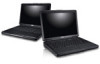
touchpad 11. cooling vents 5. memory card reader 12. network connector 6. HDMI connector 8. device status lights 14. Fan noise is running. microphone 10. power button Figure 2. security cable slot 2. Restricting the airflow can damage the computer or cause a fire...as a closed briefcase, while it is normal and does not indicate a problem with the fan or the computer. 2 The computer turns on the fan when the computer gets hot. keyboard 15. Do not store your Dell computer in the air vents. touchpad buttons (2) 13. 7. optical drive eject button 8. power...
touchpad 11. cooling vents 5. memory card reader 12. network connector 6. HDMI connector 8. device status lights 14. Fan noise is running. microphone 10. power button Figure 2. security cable slot 2. Restricting the airflow can damage the computer or cause a fire...as a closed briefcase, while it is normal and does not indicate a problem with the fan or the computer. 2 The computer turns on the fan when the computer gets hot. keyboard 15. Do not store your Dell computer in the air vents. touchpad buttons (2) 13. 7. optical drive eject button 8. power...
User Manual
Page 4
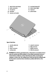
...begin any of the procedures in this section, read the safety information that shipped with your Dell computer in the air vents. cooling vents 5. USB 2.0 connector 9. Fan noise is running. However, power connectors and power strips vary among countries. battery 3. VGA... connector 7. Figure 4. For additional best practices information, see www.dell.com/regulatory_compliance. Using an incompatible cable or improperly ...
...begin any of the procedures in this section, read the safety information that shipped with your Dell computer in the air vents. cooling vents 5. USB 2.0 connector 9. Fan noise is running. However, power connectors and power strips vary among countries. battery 3. VGA... connector 7. Figure 4. For additional best practices information, see www.dell.com/regulatory_compliance. Using an incompatible cable or improperly ...
Owners Manual
Page 4
... USB Board 35 Installing The USB Board 36 14 Removing The Microphone 37 Installing The Microphone 38 15 Removing The CPU Fan Assembly And The Heatsink 39 Installing The CPU Fan Assembly And The Heatsink 40 16 Removing The Processor 41 Installing The Processor 42 17 Removing The System Board 43 Installing...
... USB Board 35 Installing The USB Board 36 14 Removing The Microphone 37 Installing The Microphone 38 15 Removing The CPU Fan Assembly And The Heatsink 39 Installing The CPU Fan Assembly And The Heatsink 40 16 Removing The Processor 41 Installing The Processor 42 17 Removing The System Board 43 Installing...
Owners Manual
Page 39
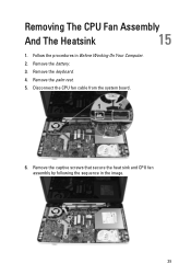
Removing The CPU Fan Assembly And The Heatsink 15 1. Remove the palm rest. 5. Remove the battery. 3. Disconnect the CPU fan cable from the system board. 6. Remove the captive screws that secure the heat sink and CPU fan assembly by following the sequence in Before Working On Your Computer. 2. Remove the keyboard. 4. Follow the procedures in the image. 39
Removing The CPU Fan Assembly And The Heatsink 15 1. Remove the palm rest. 5. Remove the battery. 3. Disconnect the CPU fan cable from the system board. 6. Remove the captive screws that secure the heat sink and CPU fan assembly by following the sequence in Before Working On Your Computer. 2. Remove the keyboard. 4. Follow the procedures in the image. 39
Owners Manual
Page 40
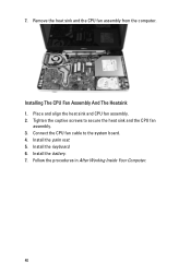
Installing The CPU Fan Assembly And The Heatsink 1. Remove the heat sink and the CPU fan assembly from the computer. Install the palm rest. 5. Follow the procedures in After Working Inside Your Computer. 40 Install the keyboard. 6. Install the battery. 7. Place and align the heat sink and CPU fan assembly. 2. Connect the CPU fan cable to secure the heat sink and the CPU fan assembly. 3. Tighten the captive screws to the system board. 4. 7.
Installing The CPU Fan Assembly And The Heatsink 1. Remove the heat sink and the CPU fan assembly from the computer. Install the palm rest. 5. Follow the procedures in After Working Inside Your Computer. 40 Install the keyboard. 6. Install the battery. 7. Place and align the heat sink and CPU fan assembly. 2. Connect the CPU fan cable to secure the heat sink and the CPU fan assembly. 3. Tighten the captive screws to the system board. 4. 7.

Owners Manual
Page 41
Follow the procedures in a counter-clockwise direction. 7. Removing The Processor 16 1. Remove the palm rest. 5. Remove the CPU fan assembly and the heatsink. 6. Lift up the processor and remove it from the computer. 41 Remove the keyboard. 4. Remove the battery. 3. Rotate the processor-cam screw in Before Working On Your Computer. 2.
Follow the procedures in a counter-clockwise direction. 7. Removing The Processor 16 1. Remove the palm rest. 5. Remove the CPU fan assembly and the heatsink. 6. Lift up the processor and remove it from the computer. 41 Remove the keyboard. 4. Remove the battery. 3. Rotate the processor-cam screw in Before Working On Your Computer. 2.
Owners Manual
Page 42
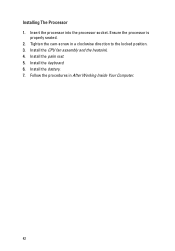
Follow the procedures in a clockwise direction to the locked position. 3. Installing The Processor 1. Install the palm rest. 5. Install the battery. 7. Tighten the cam-screw in After Working Inside Your Computer. 42 Install the CPU fan assembly and the heatsink. 4. Ensure the processor is properly seated. 2. Install the keyboard. 6. Insert the processor into the processor socket.
Follow the procedures in a clockwise direction to the locked position. 3. Installing The Processor 1. Install the palm rest. 5. Install the battery. 7. Tighten the cam-screw in After Working Inside Your Computer. 42 Install the CPU fan assembly and the heatsink. 4. Ensure the processor is properly seated. 2. Install the keyboard. 6. Insert the processor into the processor socket.
Owners Manual
Page 43
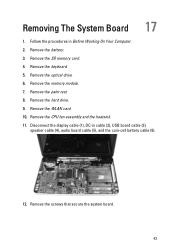
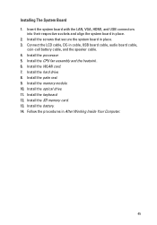
Remove the keyboard. 5. Remove the WLAN card. 10. Remove the hard drive. 9. Remove the CPU fan assembly and the heatsink. 11. Remove the optical drive. 6. Remove the palm rest. 8. Remove the memory module. 7. Follow the procedures in cable (2), USB board cable (3), speaker cable (4), audio board cable (5), and the coin-cell battery cable (6). 12. Remove the battery. 3. Remove the SD memory card. 4. Disconnect the display cable (1), DC-in Before Working On Your Computer. 2. Removing The System Board 17 1. Remove the screws that secure the system board. 43
Remove the keyboard. 5. Remove the WLAN card. 10. Remove the hard drive. 9. Remove the CPU fan assembly and the heatsink. 11. Remove the optical drive. 6. Remove the palm rest. 8. Remove the memory module. 7. Follow the procedures in cable (2), USB board cable (3), speaker cable (4), audio board cable (5), and the coin-cell battery cable (6). 12. Remove the battery. 3. Remove the SD memory card. 4. Disconnect the display cable (1), DC-in Before Working On Your Computer. 2. Removing The System Board 17 1. Remove the screws that secure the system board. 43
Owners Manual
Page 45
... Working Inside Your Computer. 45 Install the memory module. 10. Install the keyboard. 12. Install the palm rest. 9. Install the battery. 14. Install the CPU fan assembly and the heatsink . 6. Install the optical drive. 11. Install the WLAN card. 7.
... Working Inside Your Computer. 45 Install the memory module. 10. Install the keyboard. 12. Install the palm rest. 9. Install the battery. 14. Install the CPU fan assembly and the heatsink . 6. Install the optical drive. 11. Install the WLAN card. 7.
Owners Manual
Page 47
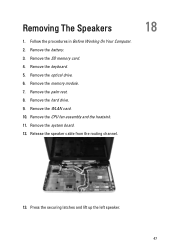
Remove the SD memory card. 4. Remove the keyboard. 5. Remove the WLAN card. 10. Follow the procedures in Before Working On Your Computer. 2. Remove the hard drive. 9. Press the securing latches and lift up the left speaker. 47 Removing The Speakers 1. Remove the memory module. 7. Remove the CPU fan assembly and the heatsink. 11. Release the speaker cable from the routing channel. 18 13. Remove the battery. 3. Remove the system board. 12. Remove the palm rest. 8. Remove the optical drive. 6.
Remove the SD memory card. 4. Remove the keyboard. 5. Remove the WLAN card. 10. Follow the procedures in Before Working On Your Computer. 2. Remove the hard drive. 9. Press the securing latches and lift up the left speaker. 47 Removing The Speakers 1. Remove the memory module. 7. Remove the CPU fan assembly and the heatsink. 11. Release the speaker cable from the routing channel. 18 13. Remove the battery. 3. Remove the system board. 12. Remove the palm rest. 8. Remove the optical drive. 6.
Owners Manual
Page 49
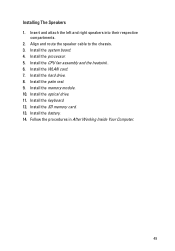
Insert and attach the left and right speakers into their respective compartments. 2. Install the memory module. 10. Follow the procedures in After Working Inside Your Computer. 49 Install the SD memory card. 13. Install the CPU fan assembly and the heatsink . 6. Install the optical drive. 11. Align and route the speaker cable to the chassis. 3. Install the processor. 5. Install the palm rest. 9. Install the system board. 4. Install the WLAN card. 7. Install the hard drive. 8. Install the keyboard. 12. Install the battery. 14. Installing The Speakers 1.
Insert and attach the left and right speakers into their respective compartments. 2. Install the memory module. 10. Follow the procedures in After Working Inside Your Computer. 49 Install the SD memory card. 13. Install the CPU fan assembly and the heatsink . 6. Install the optical drive. 11. Align and route the speaker cable to the chassis. 3. Install the processor. 5. Install the palm rest. 9. Install the system board. 4. Install the WLAN card. 7. Install the hard drive. 8. Install the keyboard. 12. Install the battery. 14. Installing The Speakers 1.


