User Manual
Page 1
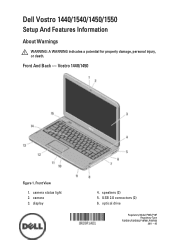
Front And Back - Front View 1. speakers (2) 5. camera status light 2. optical drive Regulatory Model P22G,P18F Regulatory Type P22G001,P22G003,P18F001,P18F002 2011 - 05 Vostro 1440/1450 Figure 1. display 4. Dell Vostro 1440/1540/1450/1550 Setup And Features Information About Warnings WARNING: A WARNING indicates a potential for property damage, personal injury, or death. camera 3. USB 2.0 connectors (2) 6.
Front And Back - Front View 1. speakers (2) 5. camera status light 2. optical drive Regulatory Model P22G,P18F Regulatory Type P22G001,P22G003,P18F001,P18F002 2011 - 05 Vostro 1440/1450 Figure 1. display 4. Dell Vostro 1440/1540/1450/1550 Setup And Features Information About Warnings WARNING: A WARNING indicates a potential for property damage, personal injury, or death. camera 3. USB 2.0 connectors (2) 6.
User Manual
Page 3
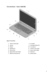
Vostro 1540/1550 Figure 3. optical drive 6. optical drive eject button 7. USB 2.0 connectors (2) 8. memory card reader 12. power button 3 camera status light 2. camera 3. microphone 11. speakers (2) 5. touchpad 9. Front View 1. touchpad buttons (2) 10. Front And Back - keyboard 14. display 4. device status lights 13.
Vostro 1540/1550 Figure 3. optical drive 6. optical drive eject button 7. USB 2.0 connectors (2) 8. memory card reader 12. power button 3 camera status light 2. camera 3. microphone 11. speakers (2) 5. touchpad 9. Front View 1. touchpad buttons (2) 10. Front And Back - keyboard 14. display 4. device status lights 13.
User Manual
Page 5
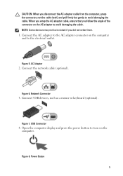
... adapter connector on the computer and to turn on the AC adapter to avoid damaging the cable. Connect the network cable (optional). Open the computer display and press the power button to the electrical outlet. Figure 5. Connect USB devices, such as a mouse or keyboard (optional). USB Connector 4. Power Button 5 NOTE: Some...
... adapter connector on the computer and to turn on the AC adapter to avoid damaging the cable. Connect the network cable (optional). Open the computer display and press the power button to the electrical outlet. Figure 5. Connect USB devices, such as a mouse or keyboard (optional). USB Connector 4. Power Button 5 NOTE: Some...
Owners Manual
Page 4
... Processor 42 17 Removing The System Board 43 Installing The System Board 45 18 Removing The Speakers 47 Installing The Speakers 49 19 Removing The Display Assembly 51 Installing The Display Assembly 53 20 Removing The DC-in Port And The Bracket 55 Installing The DC-in Port And Bracket 57
... Processor 42 17 Removing The System Board 43 Installing The System Board 45 18 Removing The Speakers 47 Installing The Speakers 49 19 Removing The Display Assembly 51 Installing The Display Assembly 53 20 Removing The DC-in Port And The Bracket 55 Installing The DC-in Port And Bracket 57
Owners Manual
Page 8
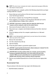
...metal at the back of your computer and certain components may appear differently than shown in this document. Close the display and turn the computer upside-down on a flat work , periodically touch an unpainted metal surface to ground the system board. Open the...Disconnect all attached devices from the appropriate slots. NOTE: To avoid damaging the system board, you must remove the main battery before opening the display. Remove the main battery. 8. CAUTION: Before touching anything inside the computer. 1. Remove any installed ExpressCards or Smart Cards from their electrical ...
...metal at the back of your computer and certain components may appear differently than shown in this document. Close the display and turn the computer upside-down on a flat work , periodically touch an unpainted metal surface to ground the system board. Open the...Disconnect all attached devices from the appropriate slots. NOTE: To avoid damaging the system board, you must remove the main battery before opening the display. Remove the main battery. 8. CAUTION: Before touching anything inside the computer. 1. Remove any installed ExpressCards or Smart Cards from their electrical ...
Owners Manual
Page 25
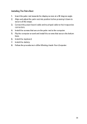
Installing The Palm Rest 1. Connect the power board cable and touchpad cable to the computer. 5. Install the screws that secure the bottom base. 6. Install the keyboard. 7. Align and adjust the palm rest into position before pressing it down to secure all the snaps. 3. Install the battery. 8. Flip the computer around and install the screws that secure the palm rest to their respective connectors. 4. Follow the procedures in After Working Inside Your Computer. 25 Insert the palm rest towards the display screen at a 30-degree angle. 2.
Installing The Palm Rest 1. Connect the power board cable and touchpad cable to the computer. 5. Install the screws that secure the bottom base. 6. Install the keyboard. 7. Align and adjust the palm rest into position before pressing it down to secure all the snaps. 3. Install the battery. 8. Flip the computer around and install the screws that secure the palm rest to their respective connectors. 4. Follow the procedures in After Working Inside Your Computer. 25 Insert the palm rest towards the display screen at a 30-degree angle. 2.
Owners Manual
Page 43
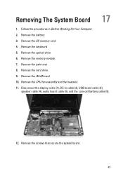
Remove the keyboard. 5. Follow the procedures in cable (2), USB board cable (3), speaker cable (4), audio board cable (5), and the coin-cell battery cable (6). 12. Remove the palm rest. 8. Remove the WLAN card. 10. Remove the screws that secure the system board. 43 Remove the memory module. 7. Remove the hard drive. 9. Remove the SD memory card. 4. Disconnect the display cable (1), DC-in Before Working On Your Computer. 2. Removing The System Board 17 1. Remove the optical drive. 6. Remove the battery. 3. Remove the CPU fan assembly and the heatsink. 11.
Remove the keyboard. 5. Follow the procedures in cable (2), USB board cable (3), speaker cable (4), audio board cable (5), and the coin-cell battery cable (6). 12. Remove the palm rest. 8. Remove the WLAN card. 10. Remove the screws that secure the system board. 43 Remove the memory module. 7. Remove the hard drive. 9. Remove the SD memory card. 4. Disconnect the display cable (1), DC-in Before Working On Your Computer. 2. Removing The System Board 17 1. Remove the optical drive. 6. Remove the battery. 3. Remove the CPU fan assembly and the heatsink. 11.

Owners Manual
Page 51
Disconnect the LVDS cable from the routing channel on the chassis. 8. Follow the procedures in Before Working On Your Computer. 2. Remove the palm rest. 6. Disconnect the WLAN antennae and release it from the system board. 7. Removing The Display Assembly 19 1. Remove the hinge cover. 4. Remove the keyboard. 5. Remove the screws that secure the left and right hinges. 51 Remove the battery. 3.
Disconnect the LVDS cable from the routing channel on the chassis. 8. Follow the procedures in Before Working On Your Computer. 2. Remove the palm rest. 6. Disconnect the WLAN antennae and release it from the system board. 7. Removing The Display Assembly 19 1. Remove the hinge cover. 4. Remove the keyboard. 5. Remove the screws that secure the left and right hinges. 51 Remove the battery. 3.

Owners Manual
Page 52
Lift up the display assembly from the computer and remove. 52 9.
Lift up the display assembly from the computer and remove. 52 9.

Owners Manual
Page 53
Insert the display assembly hinges into their holders. 2. Align the WLAN antennae routing cable to its holder and connect the antennae to the system board. 4. Connect the USB board cable. 6. Install the keyboard. 8. Connect the LVDS cable to the WLAN card. 5. Install the palm rest. 7. Installing The Display Assembly 1. Install the screws that secure both the hinges in After Working Inside Your Computer. 53 Install the hinge cover. 9. Follow the procedures in place. 3. Install the battery. 10.
Insert the display assembly hinges into their holders. 2. Align the WLAN antennae routing cable to its holder and connect the antennae to the system board. 4. Connect the USB board cable. 6. Install the keyboard. 8. Connect the LVDS cable to the WLAN card. 5. Install the palm rest. 7. Installing The Display Assembly 1. Install the screws that secure both the hinges in After Working Inside Your Computer. 53 Install the hinge cover. 9. Follow the procedures in place. 3. Install the battery. 10.

Owners Manual
Page 55
Follow the procedures in cable from the system board. 8. Remove the display assembly 7. Remove the palm rest. 6. Disconnect the DC-in Before Working On Your Computer. 2. Remove the screw that secures the DC-in Port And The Bracket 20 1. Remove the keyboard. 5. Remove the battery. 3. Removing The DC-in port and bracket. 55 Remove the hinge cover. 4.
Follow the procedures in cable from the system board. 8. Remove the display assembly 7. Remove the palm rest. 6. Disconnect the DC-in Before Working On Your Computer. 2. Remove the screw that secures the DC-in Port And The Bracket 20 1. Remove the keyboard. 5. Remove the battery. 3. Removing The DC-in port and bracket. 55 Remove the hinge cover. 4.

Owners Manual
Page 57
Insert the DC-in After Working Inside Your Computer. 57 Install the hinge cover. 8. Install the keyboard. 7. Follow the procedures in port and the bracket into its compartment. 2. Align the bracket and tighten the screw that secures the bracket and DC-in cable to the system board. 4. Install the battery. 9. Connect the DC-in port. 3. Install the palm rest. 6. Install the display assembly. 5. Installing The DC-in Port And Bracket 1.
Insert the DC-in After Working Inside Your Computer. 57 Install the hinge cover. 8. Install the keyboard. 7. Follow the procedures in port and the bracket into its compartment. 2. Align the bracket and tighten the screw that secures the bracket and DC-in cable to the system board. 4. Install the battery. 9. Connect the DC-in port. 3. Install the palm rest. 6. Install the display assembly. 5. Installing The DC-in Port And Bracket 1.

Owners Manual
Page 59
Removing The Display Bezel 21 1. Remove the bezel from the display assembly and work your way to the right and the left corners of the display bezel. 4. Starting from the bottom , pry the bezel inside out from the display assembly once all the snaps have been loosened. 59 Follow the procedures in Before Working On Your Computer. 2. Remove the battery. 3.
Removing The Display Bezel 21 1. Remove the bezel from the display assembly and work your way to the right and the left corners of the display bezel. 4. Starting from the bottom , pry the bezel inside out from the display assembly once all the snaps have been loosened. 59 Follow the procedures in Before Working On Your Computer. 2. Remove the battery. 3.
Owners Manual
Page 60
Align the display bezel in After Working Inside Your Computer. 60 Follow the procedures in line with the top cover. 2. Installing The Display Bezel 1. Starting from the bottom edge, press downward on the display bezel to engage the tabs. 3. Install the battery. 4.
Align the display bezel in After Working Inside Your Computer. 60 Follow the procedures in line with the top cover. 2. Installing The Display Bezel 1. Starting from the bottom edge, press downward on the display bezel to engage the tabs. 3. Install the battery. 4.

Owners Manual
Page 61
Disconnect the camera cable from the camera module. 22 5. Follow the procedures in Before Working On Your Computer. 2. Remove the battery. 3. Remove the display bezel. 4. Removing The Camera 1. Pry the latch, lift up the camera, and remove. 61
Disconnect the camera cable from the camera module. 22 5. Follow the procedures in Before Working On Your Computer. 2. Remove the battery. 3. Remove the display bezel. 4. Removing The Camera 1. Pry the latch, lift up the camera, and remove. 61

Owners Manual
Page 62
Connect the camera cable to its compartment. 2. Install the battery. 5. Insert and align the camera module to the camera module. 3. Install the display bezel. 4. Installing The Camera 1. Follow the procedures in After Working Inside Your Computer. 62
Connect the camera cable to its compartment. 2. Install the battery. 5. Insert and align the camera module to the camera module. 3. Install the display bezel. 4. Installing The Camera 1. Follow the procedures in After Working Inside Your Computer. 62

Owners Manual
Page 63
Removing The Display Panel 1. Disconnect the camera cable from the camera module. 23 9. Remove the battery. 3. Remove the keyboard. 5. Remove the display assembly. 7. Remove the display bezel. 8. Remove the screws that secure the display brackets and hinges. 63 Remove the palm rest. 6. Remove the hinge cover. 4. Follow the procedures in Before Working On Your Computer. 2.
Removing The Display Panel 1. Disconnect the camera cable from the camera module. 23 9. Remove the battery. 3. Remove the keyboard. 5. Remove the display assembly. 7. Remove the display bezel. 8. Remove the screws that secure the display brackets and hinges. 63 Remove the palm rest. 6. Remove the hinge cover. 4. Follow the procedures in Before Working On Your Computer. 2.
Owners Manual
Page 64
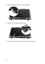
10. Lift up the display panel and brackets from the right hinge. 11. Release the wireless antennae from the display top cover. 64 Release the LVDS cable from the left hinge. 12.
10. Lift up the display panel and brackets from the right hinge. 11. Release the wireless antennae from the display top cover. 64 Release the LVDS cable from the left hinge. 12.

Owners Manual
Page 65
Remove the screws on the left and right display brackets and remove the display panel. 65 13.
Remove the screws on the left and right display brackets and remove the display panel. 65 13.

Owners Manual
Page 66
... in After Working Inside Your Computer. 66 Install the battery. 13. Installing The Display Panel 1. Align the WLAN antennae routing cable to its brackets to the display panel and secure the screws. 2. Install the display bezel. 8. Install the palm rest. 10. Install the hinge cover. 12. ...Connect the camera cable to the WLAN card. 5. Align the display panel with its holder and connect the antennae...
... in After Working Inside Your Computer. 66 Install the battery. 13. Installing The Display Panel 1. Align the WLAN antennae routing cable to its brackets to the display panel and secure the screws. 2. Install the display bezel. 8. Install the palm rest. 10. Install the hinge cover. 12. ...Connect the camera cable to the WLAN card. 5. Align the display panel with its holder and connect the antennae...


