
Owner's Manual
Page 7
...the Wireless Network Card 81 Mobile Broadband/Wireless Wide Area Network (WWAN 82 What You Need to Establish a Mobile Broadband Network Connection 82 Checking Your Dell Mobile Broadband Card . . . . 83 Microsoft® Windows® Firewall 83 10 Securing Your Computer 85 Security Cable Lock 85 Passwords 85 ...Computer Tracking Software 86 If Your Computer Is Lost or Stolen 86 11 Adding and Replacing Parts 89 Before You Begin 89 Recommended Tools 89 Turning Off Your Computer 89 Before Working Inside Your Computer 90 Optical Drive 92 Hard ...
...the Wireless Network Card 81 Mobile Broadband/Wireless Wide Area Network (WWAN 82 What You Need to Establish a Mobile Broadband Network Connection 82 Checking Your Dell Mobile Broadband Card . . . . 83 Microsoft® Windows® Firewall 83 10 Securing Your Computer 85 Security Cable Lock 85 Passwords 85 ...Computer Tracking Software 86 If Your Computer Is Lost or Stolen 86 11 Adding and Replacing Parts 89 Before You Begin 89 Recommended Tools 89 Turning Off Your Computer 89 Before Working Inside Your Computer 90 Optical Drive 92 Hard ...

Owner's Manual
Page 10
Video and Display Problems 141 If the display is blank 141 If the display is difficult to read 142 If only part of the display is readable 143 Drivers 143 What Is a Driver 143 Identifying Drivers 143 Reinstalling Drivers and Utilities 144 Troubleshooting Software ... Your Microsoft® Windows® XP Operating System 153 Using Microsoft Windows System Restore. . . . 154 Using Dell™ PC Restore 155 Using the Operating System Media 157 13 Dell™ QuickSet Features 159 14 Traveling With Your Computer 161 Identifying Your Computer 161 Packing the Computer 161 10 Contents
Video and Display Problems 141 If the display is blank 141 If the display is difficult to read 142 If only part of the display is readable 143 Drivers 143 What Is a Driver 143 Identifying Drivers 143 Reinstalling Drivers and Utilities 144 Troubleshooting Software ... Your Microsoft® Windows® XP Operating System 153 Using Microsoft Windows System Restore. . . . 154 Using Dell™ PC Restore 155 Using the Operating System Media 157 13 Dell™ QuickSet Features 159 14 Traveling With Your Computer 161 Identifying Your Computer 161 Packing the Computer 161 10 Contents

Owner's Manual
Page 43
... one screen to change, or under or pick a Control Panel icon, click Display. 5 In the Display Properties window, click the Settings tab. To view the parts of your computer is higher than the display supports, the settings adjust automatically to resize your operating system documentation. 6 Click the monitor 2 icon, click the...
... one screen to change, or under or pick a Control Panel icon, click Display. 5 In the Display Properties window, click the Settings tab. To view the parts of your computer is higher than the display supports, the settings adjust automatically to resize your operating system documentation. 6 Click the monitor 2 icon, click the...
Owner's Manual
Page 89
... Start button, and then click Turn Off Computer. The computer turns off after the operating system shutdown process finishes. Adding and Replacing Parts 89 Unless otherwise noted, each procedure assumes that the following tools: • Small flat-blade screwdriver • Phillips screwdriver •...). • You have read the safety information in reverse order. Adding and Replacing Parts Before You Begin This chapter provides procedures for removing and installing the components in your Dell™ Product Information Guide. • A component can be replaced or-if purchased ...
... Start button, and then click Turn Off Computer. The computer turns off after the operating system shutdown process finishes. Adding and Replacing Parts 89 Unless otherwise noted, each procedure assumes that the following tools: • Small flat-blade screwdriver • Phillips screwdriver •...). • You have read the safety information in reverse order. Adding and Replacing Parts Before You Begin This chapter provides procedures for removing and installing the components in your Dell™ Product Information Guide. • A component can be replaced or-if purchased ...
Owner's Manual
Page 90
Damage due to servicing that is not authorized by Dell is flat and clean to avoid bending any telephone or network cables from the battery bay before you connect a cable, ensure that both connectors are ... by its edges, not by your computer from potential damage and to help prevent damage to the computer, use other batteries designed for this particular Dell computer. NOTICE: To help ensure your computer. NOTICE: To help prevent damage to help protect your warranty. Do not use only the battery designed for...
Damage due to servicing that is not authorized by Dell is flat and clean to avoid bending any telephone or network cables from the battery bay before you connect a cable, ensure that both connectors are ... by its edges, not by your computer from potential damage and to help prevent damage to the computer, use other batteries designed for this particular Dell computer. NOTICE: To help ensure your computer. NOTICE: To help prevent damage to help protect your warranty. Do not use only the battery designed for...
Owner's Manual
Page 91
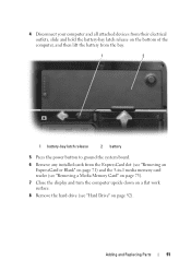
Adding and Replacing Parts 91 4 Disconnect your computer and all attached devices from their electrical outlets, slide and hold the battery-bay latch release on the bottom of the ...
Adding and Replacing Parts 91 4 Disconnect your computer and all attached devices from their electrical outlets, slide and hold the battery-bay latch release on the bottom of the ...
Owner's Manual
Page 92
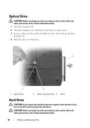
... Drive CAUTION: Before you begin any of the procedures in this section, follow the safety instructions in the Product Information Guide. 92 Adding and Replacing Parts
... Drive CAUTION: Before you begin any of the procedures in this section, follow the safety instructions in the Product Information Guide. 92 Adding and Replacing Parts

Owner's Manual
Page 93
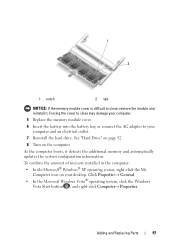
... hard drives from a source other than Dell, you need to install an operating system, drivers, and utilities on page 89. 2 Turn the computer over, and remove the hard drive screws. 1 2 1 hard drive screws (2) 2 hard drive Adding and Replacing Parts 93 See "Restoring Your Microsoft®... Windows Vista® Operating System" on page 148 and "Reinstalling Drivers and Utilities" on page 89) before removing the hard drive. NOTICE: Hard drives are installing a hard drive from sources other than Dell. To replace the...
... hard drives from a source other than Dell, you need to install an operating system, drivers, and utilities on page 89. 2 Turn the computer over, and remove the hard drive screws. 1 2 1 hard drive screws (2) 2 hard drive Adding and Replacing Parts 93 See "Restoring Your Microsoft®... Windows Vista® Operating System" on page 148 and "Reinstalling Drivers and Utilities" on page 89) before removing the hard drive. NOTICE: Hard drives are installing a hard drive from sources other than Dell. To replace the...

Owner's Manual
Page 94
... you use excessive force, you may be damaged in transit. 2 1 1 foam packaging 2 hard drive 94 Adding and Replacing Parts Returning a Hard Drive to Dell Return your old hard drive to slide the drive into the bay until it in protective antistatic packaging. See "Protecting Against Electrostatic ...hard drive out of the computer. 4 Remove the new drive from its original or comparable foam packaging. NOTICE: Use firm and even pressure to Dell in its packaging. Otherwise, the hard drive may damage the connector. 5 Slide the hard drive into place. See "Restoring Your Microsoft® ...
... you use excessive force, you may be damaged in transit. 2 1 1 foam packaging 2 hard drive 94 Adding and Replacing Parts Returning a Hard Drive to Dell Return your old hard drive to slide the drive into the bay until it in protective antistatic packaging. See "Protecting Against Electrostatic ...hard drive out of the computer. 4 Remove the new drive from its original or comparable foam packaging. NOTICE: Use firm and even pressure to Dell in its packaging. Otherwise, the hard drive may damage the connector. 5 Slide the hard drive into place. See "Restoring Your Microsoft® ...

Owner's Manual
Page 95
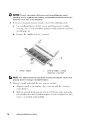
... Product Information Guide. You can increase your computer memory by installing memory modules on the memory supported by your computer. NOTE: Memory modules purchased from Dell are intended for information on the system board. NOTICE: To prevent damage to the memory module connector, do not use tools to spread the memory... captive screws on the memory module cover, and then remove the memory module cover. See "Specifications" on page 167 for your computer. Adding and Replacing Parts 95
... Product Information Guide. You can increase your computer memory by installing memory modules on the memory supported by your computer. NOTE: Memory modules purchased from Dell are intended for information on the system board. NOTICE: To prevent damage to the memory module connector, do not use tools to spread the memory... captive screws on the memory module cover, and then remove the memory module cover. See "Specifications" on page 167 for your computer. Adding and Replacing Parts 95
Owner's Manual
Page 96
... your fingertips to carefully spread apart the memory-module securing clips on the back of the memory module connector until it . 96 Adding and Replacing Parts NOTICE: To avoid electrostatic discharge, ground yourself by using a wrist grounding strap or by periodically touching an unpainted metal surface (such as a connector on each...
... your fingertips to carefully spread apart the memory-module securing clips on the back of the memory module connector until it . 96 Adding and Replacing Parts NOTICE: To avoid electrostatic discharge, ground yourself by using a wrist grounding strap or by periodically touching an unpainted metal surface (such as a connector on each...
Owner's Manual
Page 97
Adding and Replacing Parts 97 To confirm the amount of memory installed in the computer: • In the Microsoft® Windows® XP operating system, right-click the My ...
Adding and Replacing Parts 97 To confirm the amount of memory installed in the computer: • In the Microsoft® Windows® XP operating system, right-click the My ...

Owner's Manual
Page 98
... Begin" on page 89. 2 Turn the computer over, loosen the captive screws on the system board, and disconnect the modem cable. 98 Adding and Replacing Parts If you ordered the optional modem at the same time that you begin any of its connector on the modem cover, and then remove the...
... Begin" on page 89. 2 Turn the computer over, loosen the captive screws on the system board, and disconnect the modem cable. 98 Adding and Replacing Parts If you ordered the optional modem at the same time that you begin any of its connector on the modem cover, and then remove the...

Owner's Manual
Page 99
Adding and Replacing Parts 99 If you feel resistance, check the connector and realign the card. c Replace the screw that secures the modem to ensure correct insertion. NOTICE: The connector is keyed to the system board. 5 Replace the modem cover. b Align the modem with the screw holes and press the modem down into the connector on system board 4 Install the replacement modem: a Connect the modem cable to the modem. 1 5 4 32 1 modem screw 4 modem 2 modem pull-tab 5 modem cable 3 modem connector on the system board.
Adding and Replacing Parts 99 If you feel resistance, check the connector and realign the card. c Replace the screw that secures the modem to ensure correct insertion. NOTICE: The connector is keyed to the system board. 5 Replace the modem cover. b Align the modem with the screw holes and press the modem down into the connector on system board 4 Install the replacement modem: a Connect the modem cable to the modem. 1 5 4 32 1 modem screw 4 modem 2 modem pull-tab 5 modem cable 3 modem connector on the system board.

Owner's Manual
Page 100
.... 1 Follow the procedures in the Product Information Guide. b Insert a scribe into the indent to right until the cover snaps into place. 100 Adding and Replacing Parts Hinge Cover CAUTION: Before you begin any of the computer). NOTICE: To avoid electrostatic discharge, ground yourself by using a wrist grounding strap or by periodically...
.... 1 Follow the procedures in the Product Information Guide. b Insert a scribe into the indent to right until the cover snaps into place. 100 Adding and Replacing Parts Hinge Cover CAUTION: Before you begin any of the computer). NOTICE: To avoid electrostatic discharge, ground yourself by using a wrist grounding strap or by periodically...

Owner's Manual
Page 101
... procedures in this section, follow the safety instructions in "Before You Begin" on page 89. 2 Open the display. 3 Remove the hinge cover. Adding and Replacing Parts 101 NOTICE: To help prevent damage to the system board, you must remove the battery from the battery bay before you begin working inside the...
... procedures in this section, follow the safety instructions in "Before You Begin" on page 89. 2 Open the display. 3 Remove the hinge cover. Adding and Replacing Parts 101 NOTICE: To help prevent damage to the system board, you must remove the battery from the battery bay before you begin working inside the...

Owner's Manual
Page 102
... and handling the keyboard. b Slightly slide the keyboard toward the back of the keyboard into place before replacing the two screws. 102 Adding and Replacing Parts NOTICE: The keycaps on the right edge near the top to the keyboard connector. 4 Remove the keyboard: a Remove the two keyboard screws.
... and handling the keyboard. b Slightly slide the keyboard toward the back of the keyboard into place before replacing the two screws. 102 Adding and Replacing Parts NOTICE: The keycaps on the right edge near the top to the keyboard connector. 4 Remove the keyboard: a Remove the two keyboard screws.

Owner's Manual
Page 103
... not already installed, go to the system board, you must remove the battery from the Mini-Card. 1 1 Mini-Card 2 2 antenna cable connectors (2) Adding and Replacing Parts 103 If you are replacing a Mini-Card, remove the existing card: a Disconnect the two antenna cables from the battery bay before you begin any of...
... not already installed, go to the system board, you must remove the battery from the Mini-Card. 1 1 Mini-Card 2 2 antenna cable connectors (2) Adding and Replacing Parts 103 If you are replacing a Mini-Card, remove the existing card: a Disconnect the two antenna cables from the battery bay before you begin any of...

Owner's Manual
Page 104
... the Mini-Card by pushing the metal securing tabs toward the back of the computer until the card clicks into place. 104 Adding and Replacing Parts
... the Mini-Card by pushing the metal securing tabs toward the back of the computer until the card clicks into place. 104 Adding and Replacing Parts

Owner's Manual
Page 105
b Connect the two antenna cables to the Mini-Card (black cable to the connector labeled "aux" and the white cable to the Mini-Card, never place cables under the card. Adding and Replacing Parts 105 NOTICE: To avoid damage to the connector labeled "main").
b Connect the two antenna cables to the Mini-Card (black cable to the connector labeled "aux" and the white cable to the Mini-Card, never place cables under the card. Adding and Replacing Parts 105 NOTICE: To avoid damage to the connector labeled "main").


