
Owner's Manual
Page 24
... device to accumulate in a low-airflow environment, such as a closed briefcase, while it will work with the device. 24 About Your Computer S E C U R I R V E N T - The computer uses fans to create airflow through the vents, which prevents the computer from overheating. For more information, see the instructions included with the security cable slot.
... device to accumulate in a low-airflow environment, such as a closed briefcase, while it will work with the device. 24 About Your Computer S E C U R I R V E N T - The computer uses fans to create airflow through the vents, which prevents the computer from overheating. For more information, see the instructions included with the security cable slot.
Owner's Manual
Page 29
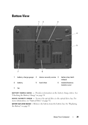
... "Optical Drive" on page 54. Bottom View 12 3 4 5 7 6 1 battery charge gauge 2 device security screw 3 battery-bay latch release 4 battery 5 hard drive 6 modem/memory module cover 7 fan B A T T E R Y C H A R G E G A U G E - Secures the optical drive in the optical drive bay. Releases the battery from the battery bay. See "Replacing the Battery" on the battery charge status...
... "Optical Drive" on page 54. Bottom View 12 3 4 5 7 6 1 battery charge gauge 2 device security screw 3 battery-bay latch release 4 battery 5 hard drive 6 modem/memory module cover 7 fan B A T T E R Y C H A R G E G A U G E - Secures the optical drive in the optical drive bay. Releases the battery from the battery bay. See "Replacing the Battery" on the battery charge status...

Owner's Manual
Page 30
..., see "Using a Battery" on page 53. For more information, see "Hard Drive" on page 92 and "Hard drive problems" on page 95. The computer uses a fan to an electrical outlet. H A R D D R I V E - M O D E M / M E M O R Y M O D U L E C O V E R - For more information, see "Modem" on page 98 and "Memory" on page 120. Covers the compartment that contains the modem and...
..., see "Using a Battery" on page 53. For more information, see "Hard Drive" on page 92 and "Hard drive problems" on page 95. The computer uses a fan to an electrical outlet. H A R D D R I V E - M O D E M / M E M O R Y M O D U L E C O V E R - For more information, see "Modem" on page 98 and "Memory" on page 120. Covers the compartment that contains the modem and...

Owner's Manual
Page 136
... hold a charge) decreases over time. Bypass power protection devices, power strips, and extension cables to an electrical outlet. 3 Turn on page 165. Turn off nearby fans, fluorescent lights, halogen lamps, or other appliances. R E S E A T THE MEMORY M O D U L E S - C HARGE THE BATTERY - If the battery status light ...computer, disconnect the computer from the electrical outlet, and then let the battery and computer cool to an electrical outlet. See "Contacting Dell" on the computer. Ensure that the light is working by testing it is low or depleted. CHECK THE AC ADAPTER - If ...
... hold a charge) decreases over time. Bypass power protection devices, power strips, and extension cables to an electrical outlet. 3 Turn on page 165. Turn off nearby fans, fluorescent lights, halogen lamps, or other appliances. R E S E A T THE MEMORY M O D U L E S - C HARGE THE BATTERY - If the battery status light ...computer, disconnect the computer from the electrical outlet, and then let the battery and computer cool to an electrical outlet. See "Contacting Dell" on the computer. Ensure that the light is working by testing it is low or depleted. CHECK THE AC ADAPTER - If ...

Owner's Manual
Page 139
... lower-right corner of your speakers have been listening to the headphone connector. If you did not turn the player volume down or off nearby fans, fluorescent lights, or halogen lamps to eliminate distortion. EL I M I N A T E P O S S I B L E I V E R - See "Reinstalling Drivers and Utilities" on page 111. Press to eliminate distortion. R E I N S T A L L T H E S O U N D...the headphone cable is securely inserted into the headphone connector (see "ExpressCards" on page 144. See "Dell Diagnostics" on page 144. Adjust the volume, bass, or treble controls to disable (mute) or ...
... lower-right corner of your speakers have been listening to the headphone connector. If you did not turn the player volume down or off nearby fans, fluorescent lights, or halogen lamps to eliminate distortion. EL I M I N A T E P O S S I B L E I V E R - See "Reinstalling Drivers and Utilities" on page 111. Press to eliminate distortion. R E I N S T A L L T H E S O U N D...the headphone cable is securely inserted into the headphone connector (see "ExpressCards" on page 144. See "Dell Diagnostics" on page 144. Adjust the volume, bass, or treble controls to disable (mute) or ...

Owner's Manual
Page 142
...change or click the Display icon. 3 Try different settings for the keyword sleep in the "Dell Diagnostics" on page 111, then contact Dell (see "Error Messages" on page 165). If no error message appears and you want to...B W O O F E R A W A Y F R O M T H E C O M P U T E R O R M O N I G H T N E S S - If your computer is at least 60 cm (2 ft) away from the computer or external monitor. Turn off nearby fans, fluorescent lights, halogen lamps, or other appliances. ADJUST THE WINDOWS DISPLAY SETTINGS - Windows Vista: 1 Click the Windows Vista Start button → Control Panel→ Hardware...
...change or click the Display icon. 3 Try different settings for the keyword sleep in the "Dell Diagnostics" on page 111, then contact Dell (see "Error Messages" on page 165). If no error message appears and you want to...B W O O F E R A W A Y F R O M T H E C O M P U T E R O R M O N I G H T N E S S - If your computer is at least 60 cm (2 ft) away from the computer or external monitor. Turn off nearby fans, fluorescent lights, halogen lamps, or other appliances. ADJUST THE WINDOWS DISPLAY SETTINGS - Windows Vista: 1 Click the Windows Vista Start button → Control Panel→ Hardware...

Owner's Manual
Page 205
...69 removing, 71 slots, 69 types, 69 WWAN, 69 H hard drive description, 26, 30 problems, 120 replacing, 92 returning to Dell, 94 hardware Dell Diagnostics, 111 Hardware Troubleshooter, 147 Help and Support Center, 17 help file Windows Help and Support Center, 17 hibernate mode, 57 hinge ...cover removing, 100 F fan description, 25, 30 Files and Settings Transfer Wizard, 33 firewall Windows XP, 83 floppy drive connecting to a USB connector...
...69 removing, 71 slots, 69 types, 69 WWAN, 69 H hard drive description, 26, 30 problems, 120 replacing, 92 returning to Dell, 94 hardware Dell Diagnostics, 111 Hardware Troubleshooter, 147 Help and Support Center, 17 help file Windows Help and Support Center, 17 hibernate mode, 57 hinge ...cover removing, 100 F fan description, 25, 30 Files and Settings Transfer Wizard, 33 firewall Windows XP, 83 floppy drive connecting to a USB connector...
Service Manual
Page 1
... NOTE indicates important information that helps you purchased a Dell n Series computer, any manner whatsoever without notice. © 2007 Dell Inc. Model PP23LB July 2007 Rev. A01 Dell™ Latitude™ 131L/Dell Vostro™ 1000 Service Manual Before You Begin Optical Drive Hard Drive ...Memory Module(s) Modem Mini-Card Keyboard Hinge Cover Display Assembly Palm Rest Coin-Cell Battery Speakers Processor Thermal-Cooling Assembly Processor Module Fan...
... NOTE indicates important information that helps you purchased a Dell n Series computer, any manner whatsoever without notice. © 2007 Dell Inc. Model PP23LB July 2007 Rev. A01 Dell™ Latitude™ 131L/Dell Vostro™ 1000 Service Manual Before You Begin Optical Drive Hard Drive ...Memory Module(s) Modem Mini-Card Keyboard Hinge Cover Display Assembly Palm Rest Coin-Cell Battery Speakers Processor Thermal-Cooling Assembly Processor Module Fan...
Service Manual
Page 21
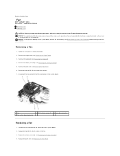
... the connector on the computer. NOTICE: To help prevent damage to the connector on the system board. 2. Back to Contents Page Fan Dell™ Latitude™ 131L/ Dell Vostro™ 1000 Service Manual Removing a Fan Replacing a Fan CAUTION: Before you begin the following procedure, follow the safety instructions in Before You Begin. 2. Remove the palm rest (see...
... the connector on the computer. NOTICE: To help prevent damage to the connector on the system board. 2. Back to Contents Page Fan Dell™ Latitude™ 131L/ Dell Vostro™ 1000 Service Manual Removing a Fan Replacing a Fan CAUTION: Before you begin the following procedure, follow the safety instructions in Before You Begin. 2. Remove the palm rest (see...
Service Manual
Page 42
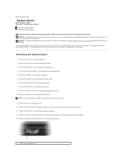
Back to Contents Page System Board Dell™ Latitude™ 131L/ Dell Vostro™ 1000 Service Manual Removing the System Board Replacing the System Board CAUTION: Before you remove the fan. 11. Remove the optical drive (see Removing the Palm Rest). Remove the palm rest (see Removing an ... 13. Remove the processor thermal-cooling assembly (see Removing the Hinge Cover). 7. Remove the memory module(s) (see Removing a Fan). 12. Remove the fan (see Removing the Memory Module(s)). 5. NOTICE: To help prevent damage to the replacement system board. Remove the keyboard (see ...
Back to Contents Page System Board Dell™ Latitude™ 131L/ Dell Vostro™ 1000 Service Manual Removing the System Board Replacing the System Board CAUTION: Before you remove the fan. 11. Remove the optical drive (see Removing the Palm Rest). Remove the palm rest (see Removing an ... 13. Remove the processor thermal-cooling assembly (see Removing the Hinge Cover). 7. Remove the memory module(s) (see Removing a Fan). 12. Remove the fan (see Removing the Memory Module(s)). 5. NOTICE: To help prevent damage to the replacement system board. Remove the keyboard (see ...
Service Manual
Page 43
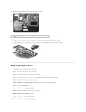
...the two hex-nut video screws in the system board. 3. Replace the processor thermal-cooling assembly (see Replacing the Display Assembly). 10. Replace the fan (see Replacing the Keyboard). 12. Pull out slightly on the system board from the system board. 1 M2.5 x 5-mm screws (2) 17.... Replace the two M2.5 x 5-mm screws in the back of the computer. 4. Replace the keyboard (see Replacing a Fan). 8. Replace the hinge cover (see Replacing the ExpressCard/Hard-Drive Bay Assembly). 5. Replace the ExpressCard/hard-drive bay assembly (see Replacing the Hinge ...
...the two hex-nut video screws in the system board. 3. Replace the processor thermal-cooling assembly (see Replacing the Display Assembly). 10. Replace the fan (see Replacing the Keyboard). 12. Pull out slightly on the system board from the system board. 1 M2.5 x 5-mm screws (2) 17.... Replace the two M2.5 x 5-mm screws in the back of the computer. 4. Replace the keyboard (see Replacing a Fan). 8. Replace the hinge cover (see Replacing the ExpressCard/Hard-Drive Bay Assembly). 5. Replace the ExpressCard/hard-drive bay assembly (see Replacing the Hinge ...


