Setup Guide
Page 5
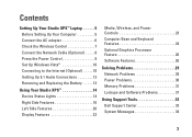
...Studio XPS™ Laptop 5 Before Setting Up Your Computer 5 Connect the AC adapter 6 Check the Wireless Control 7 Connect the Network Cable (Optional 8 Press the Power Control 9 Set Up Windows Vista 10 Connecting to the Internet (Optional 10 Setting Up 5.1 Audio Connections 12 Removing and Replacing the Battery 13 Using Your Studio XPS... 14 Device Status Lights 14 Right Side Features 16 Left Side Features 20 Display Features 22 Media, Wireless, and Power Controls 23 Computer Base and Keyboard Features 24 Optional ...
...Studio XPS™ Laptop 5 Before Setting Up Your Computer 5 Connect the AC adapter 6 Check the Wireless Control 7 Connect the Network Cable (Optional 8 Press the Power Control 9 Set Up Windows Vista 10 Connecting to the Internet (Optional 10 Setting Up 5.1 Audio Connections 12 Removing and Replacing the Battery 13 Using Your Studio XPS... 14 Device Status Lights 14 Right Side Features 16 Left Side Features 20 Display Features 22 Media, Wireless, and Power Controls 23 Computer Base and Keyboard Features 24 Optional ...
Setup Guide
Page 36
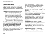
...dell.com or see "Contacting Dell" on the Dell Support website at support.dell.com or see "Contacting Dell" on page 47 for assistance. CPU fan failure - See the Service Manual on page 47 for assistance. Alert! Replace the battery. Replace the CPU fan. Hard-disk drive failure - Hard-disk drive read failure - Keyboard...to complete the boot routine some consecutive number of times for the same error, see "Contacting Dell" on page 47 for assistance. Keyboard has failed or the keyboard cable is loose, or no bootable device exists. 34 CMOS checksum error - See the ...
...dell.com or see "Contacting Dell" on the Dell Support website at support.dell.com or see "Contacting Dell" on page 47 for assistance. CPU fan failure - See the Service Manual on page 47 for assistance. Alert! Replace the battery. Replace the CPU fan. Hard-disk drive failure - Hard-disk drive read failure - Keyboard...to complete the boot routine some consecutive number of times for the same error, see "Contacting Dell" on page 47 for assistance. Keyboard has failed or the keyboard cable is loose, or no bootable device exists. 34 CMOS checksum error - See the ...
Owner's Manual (PDF)
Page 7
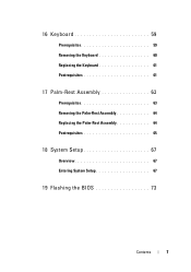
16 Keyboard 59 Prerequisites 59 Removing the Keyboard 60 Replacing the Keyboard 61 Postrequisites 61 17 Palm-Rest Assembly 63 Prerequisites 63 Removing the Palm-Rest Assembly 64 Replacing the Palm-Rest Assembly 64 Postrequisites 65 18 System Setup 67 Overview 67 Entering System Setup 67 19 Flashing the BIOS 73 Contents 7
16 Keyboard 59 Prerequisites 59 Removing the Keyboard 60 Replacing the Keyboard 61 Postrequisites 61 17 Palm-Rest Assembly 63 Prerequisites 63 Removing the Palm-Rest Assembly 64 Replacing the Palm-Rest Assembly 64 Postrequisites 65 18 System Setup 67 Overview 67 Entering System Setup 67 19 Flashing the BIOS 73 Contents 7
Owner's Manual (PDF)
Page 44
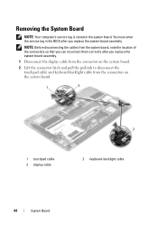
...: Before disconnecting the cables from the system board, note the location of the connectors so that you can reconnect them correctly after you replace the system-board assembly. 1 Disconnect the display cable from the connector on the system board. 2 Lift the connector latch and pull the... pull-tab to disconnect the touchpad cable and keyboard-backlight cable from the connectors on the system board. 1 2 1 touchpad cable 3 display cable 3 2 keyboard-backlight cable 44 System Board You must enter the service tag in the system board.
...: Before disconnecting the cables from the system board, note the location of the connectors so that you can reconnect them correctly after you replace the system-board assembly. 1 Disconnect the display cable from the connector on the system board. 2 Lift the connector latch and pull the... pull-tab to disconnect the touchpad cable and keyboard-backlight cable from the connectors on the system board. 1 2 1 touchpad cable 3 display cable 3 2 keyboard-backlight cable 44 System Board You must enter the service tag in the system board.
Owner's Manual (PDF)
Page 46
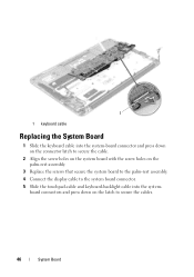
1 1 keyboard cable Replacing the System Board 1 Slide the keyboard cable into the system- board connectors and press down on the connector latch to secure the cable. 2 Align the screw holes on the system board with the screw holes on the latch to the system board connector. 5 Slide the touchpad-cable and keyboard-backlight cable into the system-board connector and press down on the palm-rest assembly. 3 Replace the screws that secure the system board to the palm-rest assembly. 4 Connect the display cable to secure the cables. 46 System Board
1 1 keyboard cable Replacing the System Board 1 Slide the keyboard cable into the system- board connectors and press down on the connector latch to secure the cable. 2 Align the screw holes on the system board with the screw holes on the latch to the system board connector. 5 Slide the touchpad-cable and keyboard-backlight cable into the system-board connector and press down on the palm-rest assembly. 3 Replace the screws that secure the system board to the palm-rest assembly. 4 Connect the display cable to secure the cables. 46 System Board
Owner's Manual (PDF)
Page 56
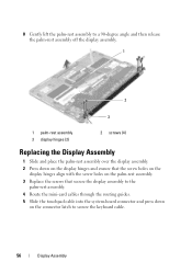
...assembly to a 90-degree angle and then release the palm-rest assembly off the display assembly. 1 2 3 1 palm-rest assembly 3 display hinges (2) 2 screws (4) Replacing the Display Assembly 1 Slide and place the palm-rest assembly over the display assembly. 2 Press down on the display hinges and ensure that the screw... holes on the display hinges align with the screw holes on the palm-rest assembly. 3 Replace the screws that secure the display assembly to the palm-rest assembly. 4 Route the mini-card cables through the routing guides. 5 Slide the...
...assembly to a 90-degree angle and then release the palm-rest assembly off the display assembly. 1 2 3 1 palm-rest assembly 3 display hinges (2) 2 screws (4) Replacing the Display Assembly 1 Slide and place the palm-rest assembly over the display assembly. 2 Press down on the display hinges and ensure that the screw... holes on the display hinges align with the screw holes on the palm-rest assembly. 3 Replace the screws that secure the display assembly to the palm-rest assembly. 4 Route the mini-card cables through the routing guides. 5 Slide the...
Owner's Manual (PDF)
Page 61
... Cover" on page 14. 12 Follow the instructions in "After Working Inside Your Computer" on page 25. 8 Replace the speakers. See "Replacing the Speakers" on the palm-rest assembly. 4 Replace the screw that secure the keyboard to the palm-rest assembly. 3 Align the screw hole on the mini-card clamp with the screw holes...
... Cover" on page 14. 12 Follow the instructions in "After Working Inside Your Computer" on page 25. 8 Replace the speakers. See "Replacing the Speakers" on the palm-rest assembly. 4 Replace the screw that secure the keyboard to the palm-rest assembly. 3 Align the screw hole on the mini-card clamp with the screw holes...

Owner's Manual (PDF)
Page 65
...-Adapter Connector" on page 25. 9 Replace the speakers. Palm-Rest Assembly 65 See "Replacing the Mini-Card" on page 37. 6 Replace the heat sink. See "Replacing the Speakers" on page 61. 2 Replace the system board. See "Replacing the Keyboard" on page 22. 10 Replace the battery. See "Replacing the Base Cover" on page 14. 13 Follow the instructions in "After...
...-Adapter Connector" on page 25. 9 Replace the speakers. Palm-Rest Assembly 65 See "Replacing the Mini-Card" on page 37. 6 Replace the heat sink. See "Replacing the Speakers" on page 61. 2 Replace the system board. See "Replacing the Keyboard" on page 22. 10 Replace the battery. See "Replacing the Base Cover" on page 14. 13 Follow the instructions in "After...


