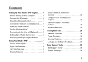
Setup Guide
Page 5
...Studio XPS™ Laptop 5 Before Setting Up Your Computer 5 Connect the AC adapter 6 Check the Wireless Control 7 Connect the Network Cable (Optional 8 Press the Power Control 9 Set Up Windows Vista 10 Connecting to the Internet (Optional 10 Setting Up 5.1 Audio Connections 12 Removing and Replacing the Battery 13 Using Your Studio XPS... 14 Device Status Lights 14 Right Side Features 16 Left Side Features 20 Display Features 22 Media, Wireless, and Power Controls 23 Computer Base and Keyboard Features 24 Optional Graphics ...
...Studio XPS™ Laptop 5 Before Setting Up Your Computer 5 Connect the AC adapter 6 Check the Wireless Control 7 Connect the Network Cable (Optional 8 Press the Power Control 9 Set Up Windows Vista 10 Connecting to the Internet (Optional 10 Setting Up 5.1 Audio Connections 12 Removing and Replacing the Battery 13 Using Your Studio XPS... 14 Device Status Lights 14 Right Side Features 16 Left Side Features 20 Display Features 22 Media, Wireless, and Power Controls 23 Computer Base and Keyboard Features 24 Optional Graphics ...
Setup Guide
Page 19
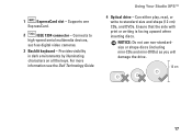
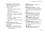
For more information see the Dell Technology Guide. Connects to standard-size and shape (12 cm) CDs, and DVDs. Using Your Studio XPS™ 4 Optical drive - Ensure that the side with print or writing is facing upward when inserting discs. Provides visibility in dark environments by illuminating characters ... the drive. 12 cm 17 NOTICE: Do not use non-standardsize or shape discs (including mini-CDs and mini-DVDs) as digital video cameras. 3 Backlit keyboard - Supports one ExpressCard. 2 IEEE 1394 connector -
For more information see the Dell Technology Guide. Connects to standard-size and shape (12 cm) CDs, and DVDs. Using Your Studio XPS™ 4 Optical drive - Ensure that the side with print or writing is facing upward when inserting discs. Provides visibility in dark environments by illuminating characters ... the drive. 12 cm 17 NOTICE: Do not use non-standardsize or shape discs (including mini-CDs and mini-DVDs) as digital video cameras. 3 Backlit keyboard - Supports one ExpressCard. 2 IEEE 1394 connector -
Setup Guide
Page 20
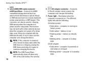
...battery. 7 Power light - computer is in power on/off or sleep state, even if they are compliant with PowerShare - Using Your Studio XPS™ 5 eSATA/USB combo connector with the USB specification. This connector can also be used for charging USB devices when the computer ...the device. Connects to eSATA compatible storage devices (such as external hard-disk drives or optical drives) or USB devices (such as a mouse, keyboard, printer, external drive, or MP3 player). battery is critically low • Blinking white - battery is low • Flashing amber - computer ...
...battery. 7 Power light - computer is in power on/off or sleep state, even if they are compliant with PowerShare - Using Your Studio XPS™ 5 eSATA/USB combo connector with the USB specification. This connector can also be used for charging USB devices when the computer ...the device. Connects to eSATA compatible storage devices (such as external hard-disk drives or optical drives) or USB devices (such as a mouse, keyboard, printer, external drive, or MP3 player). battery is critically low • Blinking white - battery is low • Flashing amber - computer ...
Setup Guide
Page 23
... a TV for HDMI. Connects to the computer. NOTE: Before you are using a cabled network signal. 5 USB connector - Using Your Studio XPS™ 3 VGA connector - battery is in sleep state On AC adapter: • Solid white - Connects to a network or broadband...to a monitor or projector. 4 Network connector - computer is powered on battery power • Solid amber - NOTE: When used as a mouse, keyboard, printer, external drive, or MP3 player. 6 DisplayPort connector - The different lights indicate the following: On battery power: • Solid white - ...
... a TV for HDMI. Connects to the computer. NOTE: Before you are using a cabled network signal. 5 USB connector - Using Your Studio XPS™ 3 VGA connector - battery is in sleep state On AC adapter: • Solid white - Connects to a network or broadband...to a monitor or projector. 4 Network connector - computer is powered on battery power • Solid amber - NOTE: When used as a mouse, keyboard, printer, external drive, or MP3 player. 6 DisplayPort connector - The different lights indicate the following: On battery power: • Solid white - ...
Setup Guide
Page 26
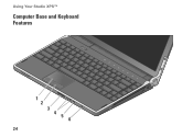
Using Your Studio XPS™ Computer Base and Keyboard Features 1 2 3 4 56 24
Using Your Studio XPS™ Computer Base and Keyboard Features 1 2 3 4 56 24
Setup Guide
Page 28
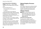
...hard drive or on the Dell Support website at support.dell.com. Optional Graphics Processor Feature Your computer features the revolutionary Hybrid SLI technology. The three lighting states are: • full keyboard/touch pad brightness • no lighting • half keyboard/touch pad brightness Touchpad ...the finger upward or downward) or the pinch zoom (zoom in this section, see the Dell Technology Guide on the right side of the taskbar. Using Your Studio XPS™ Backlit Keyboard/Touch Pad Brightness Settings - Press keys to toggle between the three lighting states (in the ...
...hard drive or on the Dell Support website at support.dell.com. Optional Graphics Processor Feature Your computer features the revolutionary Hybrid SLI technology. The three lighting states are: • full keyboard/touch pad brightness • no lighting • half keyboard/touch pad brightness Touchpad ...the finger upward or downward) or the pinch zoom (zoom in this section, see the Dell Technology Guide on the right side of the taskbar. Using Your Studio XPS™ Backlit Keyboard/Touch Pad Brightness Settings - Press keys to toggle between the three lighting states (in the ...
Setup Guide
Page 33
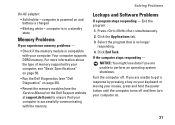
... to perform an operating system shutdown. Click the Applications tab. 3. Turn the computer off and then turn your computer on your keyboard or moving your computer. Press simultaneously. 2. If the computer stops responding - Solving Problems Lockups and Software Problems If a program stops...AC adapter: • Solid white - Select the program that your computer, see "Basic Specifications" on page 50. • Run the Dell Diagnostics (see "Dell Diagnostics" on page 36). • Reseat the memory modules (see the Service Manual on and battery is no longer responding. 4. computer...
... to perform an operating system shutdown. Click the Applications tab. 3. Turn the computer off and then turn your computer on your keyboard or moving your computer. Press simultaneously. 2. If the computer stops responding - Solving Problems Lockups and Software Problems If a program stops...AC adapter: • Solid white - Select the program that your computer, see "Basic Specifications" on page 50. • Run the Dell Diagnostics (see "Dell Diagnostics" on page 36). • Reseat the memory modules (see the Service Manual on and battery is no longer responding. 4. computer...
Setup Guide
Page 34
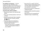
If you are unable to get a response by pressing a key on your keyboard or moving your pointer or mouse, press and hold the power button until the computer turns off . Turn the computer off and then turn your ...
If you are unable to get a response by pressing a key on your keyboard or moving your pointer or mouse, press and hold the power button until the computer turns off . Turn the computer off and then turn your ...
Setup Guide
Page 36
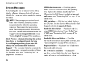
Previous attempts at booting this checkpoint and contact Dell Technical Support - CPU fan failure - Keyboard has failed or the keyboard cable is not listed in resolving this problem, please note this system have failed at support.dell.com or see "Contacting Dell" on page 47 for assistance. NOTE: If the message you received is loose. Alert...
Previous attempts at booting this checkpoint and contact Dell Technical Support - CPU fan failure - Keyboard has failed or the keyboard cable is not listed in resolving this problem, please note this system have failed at support.dell.com or see "Contacting Dell" on page 47 for assistance. NOTE: If the message you received is loose. Alert...
Setup Guide
Page 41
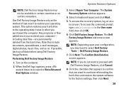
... Image Restore. The System Recovery Options window appears. 4. Click Dell Factory Image Restore. The Confirm Data Deletion screen appears. Select a keyboard layout and click Next. 5. Click Next. When the Dell logo appears, press several times to select Dell Factory Tools→ Dell Factory Image Restore. 7. Any programs or files added since you do not want...
... Image Restore. The System Recovery Options window appears. 4. Click Dell Factory Image Restore. The Confirm Data Deletion screen appears. Select a keyboard layout and click Next. 5. Click Next. When the Dell logo appears, press several times to select Dell Factory Tools→ Dell Factory Image Restore. 7. Any programs or files added since you do not want...
Setup Guide
Page 48
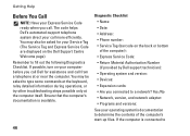
...call more efficiently. You may be asked to 46 Ensure that the computer's documentation is connected to type some commands at the keyboard, relay detailed information during operations, or try other troubleshooting steps possible only at or near the computer. Yes /No •...• Phone number: • Service Tag (barcode on the back or bottom of the computer's start-up files. The code helps Dell's automated-support telephone system direct your operating system's documentation to fill out the following Diagnostics Checklist. Remember to determine the contents of the ...
...call more efficiently. You may be asked to 46 Ensure that the computer's documentation is connected to type some commands at the keyboard, relay detailed information during operations, or try other troubleshooting steps possible only at or near the computer. Yes /No •...• Phone number: • Service Tag (barcode on the back or bottom of the computer's start-up files. The code helps Dell's automated-support telephone system direct your operating system's documentation to fill out the following Diagnostics Checklist. Remember to determine the contents of the ...

Setup Guide
Page 56
... and Canada); Pixel pitch 0.2235 mm Controls brightness can be controlled through keyboard shortcuts (see the Dell Technology Guide for more information) Keyboard (Backlit) Number of 86/103 (U.S. cd/m² (CCFL 5 point ...avg) Display Viewing Angles: Horizontal ±40° (CCFL) min. ±50° (LED) min. Basic Specifications Display Type (AntiGlare) Dimensions: Height Width Diagonal Maximum resolution Refresh rate Operating angle Luminance 13.3-inch WXGA WLED 13...
... and Canada); Pixel pitch 0.2235 mm Controls brightness can be controlled through keyboard shortcuts (see the Dell Technology Guide for more information) Keyboard (Backlit) Number of 86/103 (U.S. cd/m² (CCFL 5 point ...avg) Display Viewing Angles: Horizontal ±40° (CCFL) min. ±50° (LED) min. Basic Specifications Display Type (AntiGlare) Dimensions: Height Width Diagonal Maximum resolution Refresh rate Operating angle Luminance 13.3-inch WXGA WLED 13...
Owner's Manual (PDF)
Page 7
16 Keyboard 59 Prerequisites 59 Removing the Keyboard 60 Replacing the Keyboard 61 Postrequisites 61 17 Palm-Rest Assembly 63 Prerequisites 63 Removing the Palm-Rest Assembly 64 Replacing the Palm-Rest Assembly 64 Postrequisites 65 18 System Setup 67 Overview 67 Entering System Setup 67 19 Flashing the BIOS 73 Contents 7
16 Keyboard 59 Prerequisites 59 Removing the Keyboard 60 Replacing the Keyboard 61 Postrequisites 61 17 Palm-Rest Assembly 63 Prerequisites 63 Removing the Palm-Rest Assembly 64 Replacing the Palm-Rest Assembly 64 Postrequisites 65 18 System Setup 67 Overview 67 Entering System Setup 67 19 Flashing the BIOS 73 Contents 7
Owner's Manual (PDF)
Page 44
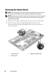
... the display cable from the connector on the system board. 2 Lift the connector latch and pull the pull-tab to disconnect the touchpad cable and keyboard-backlight cable from the system board, note the location of the connectors so that you can reconnect them correctly after you replace the system-board...
... the display cable from the connector on the system board. 2 Lift the connector latch and pull the pull-tab to disconnect the touchpad cable and keyboard-backlight cable from the system board, note the location of the connectors so that you can reconnect them correctly after you replace the system-board...
Owner's Manual (PDF)
Page 45
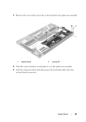
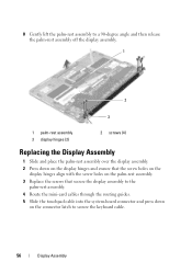
System Board 45 3 Remove the screws that secure the system board to the palm-rest assembly. 2 1 1 system board 2 screws (4) 4 Turn the system board over and place it over the palm-rest assembly. 5 Lift the connector latch and disconnect the keyboard cable from the system board connector.
System Board 45 3 Remove the screws that secure the system board to the palm-rest assembly. 2 1 1 system board 2 screws (4) 4 Turn the system board over and place it over the palm-rest assembly. 5 Lift the connector latch and disconnect the keyboard cable from the system board connector.
Owner's Manual (PDF)
Page 46
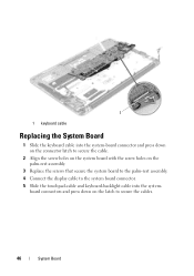
board connectors and press down on the palm-rest assembly. 3 Replace the screws that secure the system board to the palm-rest assembly. 4 Connect the display cable to the system board connector. 5 Slide the touchpad-cable and keyboard-backlight cable into the system-board connector and press down on the connector latch to secure the cable. 2 Align the screw holes on the system board with the screw holes on the latch to secure the cables. 46 System Board 1 1 keyboard cable Replacing the System Board 1 Slide the keyboard cable into the system-
board connectors and press down on the palm-rest assembly. 3 Replace the screws that secure the system board to the palm-rest assembly. 4 Connect the display cable to the system board connector. 5 Slide the touchpad-cable and keyboard-backlight cable into the system-board connector and press down on the connector latch to secure the cable. 2 Align the screw holes on the system board with the screw holes on the latch to secure the cables. 46 System Board 1 1 keyboard cable Replacing the System Board 1 Slide the keyboard cable into the system-
Owner's Manual (PDF)
Page 56
...-card cables through the routing guides. 5 Slide the touchpad cable into the system-board connector and press down on the connector latch to secure the keyboard cable. 56 Display Assembly
...-card cables through the routing guides. 5 Slide the touchpad cable into the system-board connector and press down on the connector latch to secure the keyboard cable. 56 Display Assembly
Owner's Manual (PDF)
Page 59
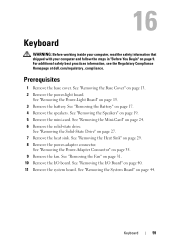
... the Power-Adapter Connector" on page 27. 7 Remove the heat sink. For additional safety best practices information, see the Regulatory Compliance Homepage at dell.com/regulatory_compliance. See "Removing the Battery" on page 29. 8 Remove the power-adapter connector. See "Removing the Heat Sink" on page 17...Remove the system board. See "Removing the Base Cover" on page 15. 3 Remove the battery. Keyboard 59 Prerequisites 1 Remove the base cover. See "Removing the Power-Light Board" on page 13. 2 Remove the power-light board. See "Removing the Mini-Card" on page 44. See "...
... the Power-Adapter Connector" on page 27. 7 Remove the heat sink. For additional safety best practices information, see the Regulatory Compliance Homepage at dell.com/regulatory_compliance. See "Removing the Battery" on page 29. 8 Remove the power-adapter connector. See "Removing the Heat Sink" on page 17...Remove the system board. See "Removing the Base Cover" on page 15. 3 Remove the battery. Keyboard 59 Prerequisites 1 Remove the base cover. See "Removing the Power-Light Board" on page 13. 2 Remove the power-light board. See "Removing the Mini-Card" on page 44. See "...
Owner's Manual (PDF)
Page 60
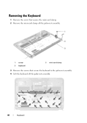
Removing the Keyboard 1 Remove the screw that secures the mini-card clamp. 2 Remove the mini-card clamp off the palm-rest assembly. 1 2 3 1 screw 3 keyboard 2 mini-card clamp 3 Remove the screws that secure the keyboard to the palm-rest assembly. 4 Lift the keyboard off the palm-rest assembly. 60 Keyboard
Removing the Keyboard 1 Remove the screw that secures the mini-card clamp. 2 Remove the mini-card clamp off the palm-rest assembly. 1 2 3 1 screw 3 keyboard 2 mini-card clamp 3 Remove the screws that secure the keyboard to the palm-rest assembly. 4 Lift the keyboard off the palm-rest assembly. 60 Keyboard
Owner's Manual (PDF)
Page 61
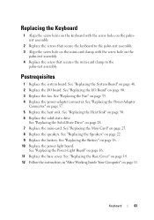
...Battery" on page 37. 5 Replace the heat sink. See "Replacing the Power-Adapter Connector" on page 18. 10 Replace the power-light board. Keyboard 61 See "Replacing the Solid-State Drive" on page 11. See "Replacing the Base Cover" on page 14. 12 Follow the instructions in "After...card clamp with the screw hole on page 22. 9 Replace the battery. Replacing the Keyboard 1 Align the screw holes on the keyboard with the screw holes on the palmrest assembly. 2 Replace the screws that secure the keyboard to the palm-rest assembly. See "Replacing the I /O board. See "Replacing the ...
...Battery" on page 37. 5 Replace the heat sink. See "Replacing the Power-Adapter Connector" on page 18. 10 Replace the power-light board. Keyboard 61 See "Replacing the Solid-State Drive" on page 11. See "Replacing the Base Cover" on page 14. 12 Follow the instructions in "After...card clamp with the screw hole on page 22. 9 Replace the battery. Replacing the Keyboard 1 Align the screw holes on the keyboard with the screw holes on the palmrest assembly. 2 Replace the screws that secure the keyboard to the palm-rest assembly. See "Replacing the I /O board. See "Replacing the ...


