
Service Manual
Page 10
.... 14. When the processor is positioned underneath the center cover latch on the system board. 19. Clean the thermal grease from the ATX POWER and ATX_CPU connectors (see Replacing the Processor Fan and Heat Sink Assembly). NOTICE: Socket pins are delicate. Replace the computer cover (see Replacing...bend the pins on the processor cover is fully seated in the socket and ensure that you install the processor. 12. Set the processor lightly in the socket, close the processor cover. NOTICE: You must position the processor correctly in the socket to avoid permanent damage to the...
.... 14. When the processor is positioned underneath the center cover latch on the system board. 19. Clean the thermal grease from the ATX POWER and ATX_CPU connectors (see Replacing the Processor Fan and Heat Sink Assembly). NOTICE: Socket pins are delicate. Replace the computer cover (see Replacing...bend the pins on the processor cover is fully seated in the socket and ensure that you install the processor. 12. Set the processor lightly in the socket, close the processor cover. NOTICE: You must position the processor correctly in the socket to avoid permanent damage to the...
Setup Guide
Page 17
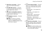
... to eject a disc from the optical drive. 5 IEEE 1394 connector - the computer is in power-on or off the computer while the hard drive activity light is in or microphone connector - Press to headphones. Using Your Studio 540 8 Power button and light - there may be a problem with the system board. • Solid amber - NOTICE: To...
... to eject a disc from the optical drive. 5 IEEE 1394 connector - the computer is in power-on or off the computer while the hard drive activity light is in or microphone connector - Press to headphones. Using Your Studio 540 8 Power button and light - there may be a problem with the system board. • Solid amber - NOTICE: To...
Setup Guide
Page 19
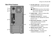
.... 6 Voltage selector switch - Attach a commercially 1 available anti-theft device. 3 Expansion card slots (4) - Indicates power availability for any installed PCI and PCI Express cards. 4 Back panel connectors - Plug USB, audio, and other devices into the appropriate connector. 2 5 Power supply light - Back View Features 7 6 5 4 3 Using Your Studio 540 1 Security cable slot - Connects your computer. 2 Padlock rings -
.... 6 Voltage selector switch - Attach a commercially 1 available anti-theft device. 3 Expansion card slots (4) - Indicates power availability for any installed PCI and PCI Express cards. 4 Back panel connectors - Plug USB, audio, and other devices into the appropriate connector. 2 5 Power supply light - Back View Features 7 6 5 4 3 Using Your Studio 540 1 Security cable slot - Connects your computer. 2 Padlock rings -

Setup Guide
Page 25
... status for the wired cable connection. Also bypass power protection devices, power strips, and power extension cables to verify that the electrical outlet is only for wireless connections. Power Problems If the power light is off or is not receiving power. • Reseat the power cable into both the power connector on the computer and the electrical outlet. •...
... status for the wired cable connection. Also bypass power protection devices, power strips, and power extension cables to verify that the electrical outlet is only for wireless connections. Power Problems If the power light is off or is not receiving power. • Reseat the power cable into both the power connector on the computer and the electrical outlet. •...

Setup Guide
Page 26
... information on removing and replacing memory modules, see "Contacting Dell" on the trackpad or a connected mouse, or press the power button to the same electrical outlet. 24 If the power light is blinking white - The computer has a power problem or an internal device malfunction. If the power light is blinking amber - Press a key on the keyboard, move...
... information on removing and replacing memory modules, see "Contacting Dell" on the trackpad or a connected mouse, or press the power button to the same electrical outlet. 24 If the power light is blinking white - The computer has a power problem or an internal device malfunction. If the power light is blinking amber - Press a key on the keyboard, move...

Setup Guide
Page 58
Index ISP Internet Service Provider 11 L line-in connector 15 M media card reader 16 memory minimum and maximum 47 memory problems solving 25 Memory Stick reader 16 memory support 47 microphone connector 15 Microsoft Windows Vista 11 MMC 16 Multi Media Card reader 16 56 N network connection fixing 23 network connector location 18 network speed testing 22 O order status 40 P power button and light 15 power connector 17 power problems, solving 23 problems, solving 22 processor 46 products information and purchasing 40
Index ISP Internet Service Provider 11 L line-in connector 15 M media card reader 16 memory minimum and maximum 47 memory problems solving 25 Memory Stick reader 16 memory support 47 microphone connector 15 Microsoft Windows Vista 11 MMC 16 Multi Media Card reader 16 56 N network connection fixing 23 network connector location 18 network speed testing 22 O order status 40 P power button and light 15 power connector 17 power problems, solving 23 problems, solving 22 processor 46 products information and purchasing 40


