
Service Manual
Page 1
... Vista start button logo are not followed. Dell Studio™ 1555 Service Manual Before You Begin Base Cover Hard Drive Memory Communication Cards Coin-Cell Battery Center Control Cover Keyboard Display Power Button Board Camera (Optional) Palm Rest Speaker Assembly Optical Drive ExpressCard Board AC Adapter Connector USB Connector System Board Assembly Processor Heat...
... Vista start button logo are not followed. Dell Studio™ 1555 Service Manual Before You Begin Base Cover Hard Drive Memory Communication Cards Coin-Cell Battery Center Control Cover Keyboard Display Power Button Board Camera (Optional) Palm Rest Speaker Assembly Optical Drive ExpressCard Board AC Adapter Connector USB Connector System Board Assembly Processor Heat...
Service Manual
Page 2
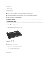
...the main battery (see "Before Working Inside Your Computer" on the base cover and lift the cover off the computer, disconnect the AC adapter from the electrical outlet and the computer, disconnect the modem from the wall connector and the computer, and remove any other external cables... clicks into place. WARNING: Before performing these procedures, turn off the computer at www.dell.com/regulatory_compliance. Back to the bottom of the computer). Back to Contents Page Base Cover Dell Studio™ 1555 Service Manual Removing the Base Cover Replacing the Base Cover WARNING: Before working...
...the main battery (see "Before Working Inside Your Computer" on the base cover and lift the cover off the computer, disconnect the AC adapter from the electrical outlet and the computer, disconnect the modem from the wall connector and the computer, and remove any other external cables... clicks into place. WARNING: Before performing these procedures, turn off the computer at www.dell.com/regulatory_compliance. Back to the bottom of the computer). Back to Contents Page Base Cover Dell Studio™ 1555 Service Manual Removing the Base Cover Replacing the Base Cover WARNING: Before working...
Service Manual
Page 5
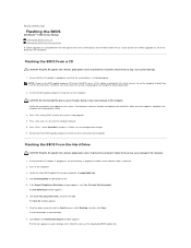
...Download Complete window appears. NOTE: If you use the BIOS-update program CD to flash the BIOS, press before inserting the CD so that the AC adapter is plugged in , the main battery is properly installed, and a network cable is attached. 2. CAUTION: Do not interrupt this program to disk... the BIOS From a CD CAUTION: Plug the AC adapter into a known, good power source to prevent loss of power. The computer continues to view the Save In menu, select Desktop, and then click Save. Back to Contents Page Flashing the BIOS Dell Studio™ 1555 Service Manual Flashing the BIOS From ...
...Download Complete window appears. NOTE: If you use the BIOS-update program CD to flash the BIOS, press before inserting the CD so that the AC adapter is plugged in , the main battery is properly installed, and a network cable is attached. 2. CAUTION: Do not interrupt this program to disk... the BIOS From a CD CAUTION: Plug the AC adapter into a known, good power source to prevent loss of power. The computer continues to view the Save In menu, select Desktop, and then click Save. Back to Contents Page Flashing the BIOS Dell Studio™ 1555 Service Manual Flashing the BIOS From ...
Service Manual
Page 13
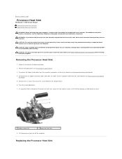
...Processor Heat Sink CAUTION: To avoid electrostatic discharge, ground yourself by using a wrist grounding strap or by your computer. Disconnect the AC adapter connector cable, USB cable, fan cable, and the subwoofer cable from the computer when the heat sink is not covered by periodically...you remove the processor heat sink from the system board (see the Regulatory Compliance Homepage at www.dell.com/regulatory_compliance. Back to Contents Page Processor Heat Sink Dell Studio™ 1555 Service Manual Removing the Processor Heat Sink Replacing the Processor Heat Sink WARNING: Before ...
...Processor Heat Sink CAUTION: To avoid electrostatic discharge, ground yourself by using a wrist grounding strap or by your computer. Disconnect the AC adapter connector cable, USB cable, fan cable, and the subwoofer cable from the computer when the heat sink is not covered by periodically...you remove the processor heat sink from the system board (see the Regulatory Compliance Homepage at www.dell.com/regulatory_compliance. Back to Contents Page Processor Heat Sink Dell Studio™ 1555 Service Manual Removing the Processor Heat Sink Replacing the Processor Heat Sink WARNING: Before ...
Service Manual
Page 14
NOTE: This procedure assumes that you have already removed the processor heat sink and are reinstalled together. Connect the AC adapter connector cable, USB cable, fan cable, and the subwoofer cable to the system board (see Replacing the Optical Drive). 7. If either the processor or heat ...
NOTE: This procedure assumes that you have already removed the processor heat sink and are reinstalled together. Connect the AC adapter connector cable, USB cable, fan cable, and the subwoofer cable to the system board (see Replacing the Optical Drive). 7. If either the processor or heat ...
Service Manual
Page 22
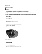
... that is not authorized by Dell™ is not covered by periodically touching an unpainted metal surface (such as a connector on the system board. Replace the six screws that secure the system board to the computer base. 7. Connect the AC adapter connector cable, USB cable, ...to Contents Page Fan Dell Studio™ 1555 Service Manual Removing the Fan Replacing the Fan WARNING: Before working inside your computer, read the safety information that shipped with your warranty. Removing the Fan 1. Follow the instructions in Before You Begin. 2. Disconnect the AC adapter connector cable, USB...
... that is not authorized by Dell™ is not covered by periodically touching an unpainted metal surface (such as a connector on the system board. Replace the six screws that secure the system board to the computer base. 7. Connect the AC adapter connector cable, USB cable, ...to Contents Page Fan Dell Studio™ 1555 Service Manual Removing the Fan Replacing the Fan WARNING: Before working inside your computer, read the safety information that shipped with your warranty. Removing the Fan 1. Follow the instructions in Before You Begin. 2. Disconnect the AC adapter connector cable, USB...
Service Manual
Page 31
... the base cover (see Replacing the Base Cover). 4. To confirm the amount of memory installed in the computer, click Start ® Help and Support® Dell System Information. Forcing the base cover to close may damage your computer and an electrical outlet. 5. module and reinstall it detects the additional memory and... not boot. 1 tab 2 notch CAUTION: If the base cover is difficult to close , remove the module and reinstall it clicks into place, or connect the AC adapter to Contents Page
... the base cover (see Replacing the Base Cover). 4. To confirm the amount of memory installed in the computer, click Start ® Help and Support® Dell System Information. Forcing the base cover to close may damage your computer and an electrical outlet. 5. module and reinstall it detects the additional memory and... not boot. 1 tab 2 notch CAUTION: If the base cover is difficult to close , remove the module and reinstall it clicks into place, or connect the AC adapter to Contents Page
Service Manual
Page 39
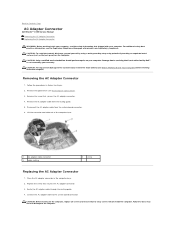
...screws and ensure that shipped with your computer. Removing the AC Adapter Connector 1. Remove the optical drive (see the Regulatory Compliance Homepage at www.dell.com/regulatory_compliance. Connect the AC adapter cable to the system board connector. CAUTION: Before turning on...2. Remove the screw that secures the AC adapter connector. 3. Place the AC adapter connector in the computer base. 2. Back to Contents Page AC Adapter Connector Dell Studio™ 1555 Service Manual Removing the AC Adapter Connector Replacing the AC Adapter Connector WARNING: Before working inside your ...
...screws and ensure that shipped with your computer. Removing the AC Adapter Connector 1. Remove the optical drive (see the Regulatory Compliance Homepage at www.dell.com/regulatory_compliance. Connect the AC adapter cable to the system board connector. CAUTION: Before turning on...2. Remove the screw that secures the AC adapter connector. 3. Place the AC adapter connector in the computer base. 2. Back to Contents Page AC Adapter Connector Dell Studio™ 1555 Service Manual Removing the AC Adapter Connector Replacing the AC Adapter Connector WARNING: Before working inside your ...
Service Manual
Page 43
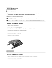
...dell.com/regulatory_compliance. Lift the system board off the computer base. 6. Place the subwoofer on your computer. CAUTION: Only a certified service technician should perform repairs on the computer base and replace the three screws securing the subwoofer to the computer base. 5. Remove the three screws on the computer base. Disconnect the AC adapter... practices information, see Removing the Optical Drive). 3. Back to Contents Page Subwoofer Assembly Dell Studio™ 1555 Service Manual Removing the Subwoofer Assembly Replacing the Subwoofer Assembly WARNING: Before working...
...dell.com/regulatory_compliance. Lift the system board off the computer base. 6. Place the subwoofer on your computer. CAUTION: Only a certified service technician should perform repairs on the computer base and replace the three screws securing the subwoofer to the computer base. 5. Remove the three screws on the computer base. Disconnect the AC adapter... practices information, see Removing the Optical Drive). 3. Back to Contents Page Subwoofer Assembly Dell Studio™ 1555 Service Manual Removing the Subwoofer Assembly Replacing the Subwoofer Assembly WARNING: Before working...

Service Manual
Page 44
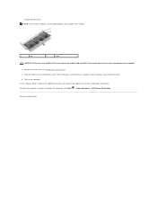
Connect the AC adapter connector cable, USB cable, fan cable, and the subwoofer cable to Contents Page Replace the optical drive (see Replacing the Optical Drive). Back to their respective connectors on the system board. 6. Replace the six screws that secure the system board to the computer base. 5. 4.
Connect the AC adapter connector cable, USB cable, fan cable, and the subwoofer cable to Contents Page Replace the optical drive (see Replacing the Optical Drive). Back to their respective connectors on the system board. 6. Replace the six screws that secure the system board to the computer base. 5. 4.
Service Manual
Page 45
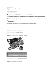
...the Palm Rest). 3. Removing the System Board Assembly 1. Remove the palm rest (see the Regulatory Compliance Homepage at www.dell.com/regulatory_compliance. CAUTION: To help prevent damage to the system board, remove the main battery (see Removing the Optical ... USB cable connector 6 subwoofer cable connector 6. Disconnect the fan cable, AC adapter cable, USB cable, ExpressCard cables, and subwoofer cable from the system board. Back to Contents Page System Board Assembly Dell Studio™ 1555 Service Manual Removing the System Board Assembly Replacing the System Board...
...the Palm Rest). 3. Removing the System Board Assembly 1. Remove the palm rest (see the Regulatory Compliance Homepage at www.dell.com/regulatory_compliance. CAUTION: To help prevent damage to the system board, remove the main battery (see Removing the Optical ... USB cable connector 6 subwoofer cable connector 6. Disconnect the fan cable, AC adapter cable, USB cable, ExpressCard cables, and subwoofer cable from the system board. Back to Contents Page System Board Assembly Dell Studio™ 1555 Service Manual Removing the System Board Assembly Replacing the System Board...
Service Manual
Page 48
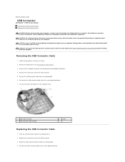
... Connect the USB connector cable to the system board, remove the main battery (see Removing the AC Adapter Connector). 4. Back to servicing that is not authorized by Dell™ is not covered by periodically touching an unpainted metal surface (such as the back panel... drive (see the Regulatory Compliance Homepage at www.dell.com/regulatory_compliance. Remove the AC adapter connector (see Before Working Inside Your Computer) before working inside the computer. Damage due to Contents Page USB Connector Dell Studio™ 1555 Service Manual Removing the USB Connector Cable...
... Connect the USB connector cable to the system board, remove the main battery (see Removing the AC Adapter Connector). 4. Back to servicing that is not authorized by Dell™ is not covered by periodically touching an unpainted metal surface (such as the back panel... drive (see the Regulatory Compliance Homepage at www.dell.com/regulatory_compliance. Remove the AC adapter connector (see Before Working Inside Your Computer) before working inside the computer. Damage due to Contents Page USB Connector Dell Studio™ 1555 Service Manual Removing the USB Connector Cable...

Service Manual
Page 49
CAUTION: Before turning on the computer, replace all screws and ensure that no stray screws remain inside the computer. Back to the computer. 5. Replace the AC adapter connector (see Replacing the Optical Drive). Failure to do so may result in damage to Contents Page Replace the optical drive (see Replacing the AC Adapter Connector). 6.
CAUTION: Before turning on the computer, replace all screws and ensure that no stray screws remain inside the computer. Back to the computer. 5. Replace the AC adapter connector (see Replacing the Optical Drive). Failure to do so may result in damage to Contents Page Replace the optical drive (see Replacing the AC Adapter Connector). 6.
Setup Guide
Page 5
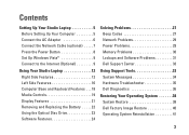
... 5 Before Setting Up Your Computer 5 Connect the AC Adapter 6 Connect the Network Cable (optional 7 Press the Power Button 8 Set Up Windows Vista 9 Connect to the Internet (Optional 9 Using Your Studio Laptop 12 Right Side Features 12 Left Side Features 16 Computer Base and Keyboard Features 18 Media Controls 19 Display Features 21 ... 23 Software Features 24 Solving Problems 27 Beep Codes 27 Network Problems 29 Power Problems 29 Memory Problems 30 Lockups and Software Problems 31 Dell Support Center 33 Using Support Tools 33 System Messages 34 Hardware Troubleshooter 35...
... 5 Before Setting Up Your Computer 5 Connect the AC Adapter 6 Connect the Network Cable (optional 7 Press the Power Button 8 Set Up Windows Vista 9 Connect to the Internet (Optional 9 Using Your Studio Laptop 12 Right Side Features 12 Left Side Features 16 Computer Base and Keyboard Features 18 Media Controls 19 Display Features 21 ... 23 Software Features 24 Solving Problems 27 Beep Codes 27 Network Problems 29 Power Problems 29 Memory Problems 30 Lockups and Software Problems 31 Dell Support Center 33 Using Support Tools 33 System Messages 34 Hardware Troubleshooter 35...
Setup Guide
Page 8
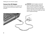
However, power connectors and power strips vary among countries. WARNING: The AC adapter works with electrical outlets worldwide. Setting Up Your Studio Laptop Connect the AC Adapter Connect the AC adapter to a power strip or electrical outlet may cause fire or equipment damage. 6 Using an incompatible cable or improperly connecting the cable to the computer and then plug it into an electrical outlet or surge protector.
However, power connectors and power strips vary among countries. WARNING: The AC adapter works with electrical outlets worldwide. Setting Up Your Studio Laptop Connect the AC Adapter Connect the AC adapter to a power strip or electrical outlet may cause fire or equipment damage. 6 Using an incompatible cable or improperly connecting the cable to the computer and then plug it into an electrical outlet or surge protector.
Setup Guide
Page 15
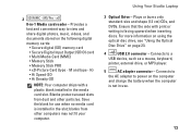
Using Your Studio Laptop 3 Optical Drive - Connects to the AC adapter to power on the computer and charge the battery when the computer is installed in the media card slot. H) • Hi Speed-SD • Hi ... card is not in -1 Media card reader - Provides a fast and convenient way to a USB device, such as a mouse, keyboard, printer, external drive, or MP3 player. 5 AC adapter connector - For more information on using the optical disc drive, see "Using the Optical Disc Drive" on the following digital memory cards: • Secure digital...
Using Your Studio Laptop 3 Optical Drive - Connects to the AC adapter to power on the computer and charge the battery when the computer is installed in the media card slot. H) • Hi Speed-SD • Hi ... card is not in -1 Media card reader - Provides a fast and convenient way to a USB device, such as a mouse, keyboard, printer, external drive, or MP3 player. 5 AC adapter connector - For more information on using the optical disc drive, see "Using the Optical Disc Drive" on the following digital memory cards: • Secure digital...
Setup Guide
Page 24
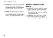
For more information about displays, see the Dell Technology Guide. This computer should only use batteries from Dell. Using Your Studio Laptop 4 Right digital array microphone (optional) - Combines with the left digital array microphone to provide high quality sound for video chatting and voice recording. 5 Display - ... your computer. Do not use a battery purchased from other computers. WARNING: Before removing the battery, shut down the computer, and remove external cables (including the AC adapter). 22
For more information about displays, see the Dell Technology Guide. This computer should only use batteries from Dell. Using Your Studio Laptop 4 Right digital array microphone (optional) - Combines with the left digital array microphone to provide high quality sound for video chatting and voice recording. 5 Display - ... your computer. Do not use a battery purchased from other computers. WARNING: Before removing the battery, shut down the computer, and remove external cables (including the AC adapter). 22
Setup Guide
Page 31
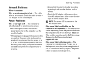
... a light, ensure that the light on the AC adapter is plugged in standby mode. Press the power button until the computer turns off and then turn it is on the Dell Support website at support.dell.com. If the problem persists, see the Dell Technology Guide on . If the power light is not ...responding - Check the cable to verify that the computer turns on properly. • Ensure that the power strip is working by testing it with another device, such as a lamp. • Check the AC adapter cable connections. The ...
... a light, ensure that the light on the AC adapter is plugged in standby mode. Press the power button until the computer turns off and then turn it is on the Dell Support website at support.dell.com. If the problem persists, see the Dell Technology Guide on . If the power light is not ...responding - Check the cable to verify that the computer turns on properly. • Ensure that the power strip is working by testing it with another device, such as a lamp. • Check the AC adapter cable connections. The ...
Setup Guide
Page 61
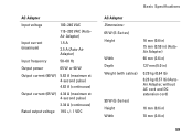
AC Adapter Input voltage Input current (maximum) Input frequency 100-240 VAC 115-230 VAC (AutoAir Adapter) 1.5 A 2.5 A (Auto-Air Adapter) 50-60 Hz Output power 65 W or 90 W Output current (90 W) 5.62 A (maximum at 4-second pulse) 4.62 A (continuous) Output current (65 W)... 4.34 A (maximum at 4-second pulse) 3.34 A (continuous) Rated output voltage 19.5 +/- 1 VDC Basic Specifications AC Adapter Dimensions: 65 W (E-Series) Height Width Depth Weight (with cables) 90 W (E-Series) Height Width 16 mm (0.6 in) 15 mm (0.59 in) (AutoAir...
AC Adapter Input voltage Input current (maximum) Input frequency 100-240 VAC 115-230 VAC (AutoAir Adapter) 1.5 A 2.5 A (Auto-Air Adapter) 50-60 Hz Output power 65 W or 90 W Output current (90 W) 5.62 A (maximum at 4-second pulse) 4.62 A (continuous) Output current (65 W)... 4.34 A (maximum at 4-second pulse) 3.34 A (continuous) Rated output voltage 19.5 +/- 1 VDC Basic Specifications AC Adapter Dimensions: 65 W (E-Series) Height Width Depth Weight (with cables) 90 W (E-Series) Height Width 16 mm (0.6 in) 15 mm (0.59 in) (AutoAir...
Setup Guide
Page 62
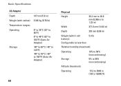
Basic Specifications AC Adapter Depth Weight (with cables) Temperature ranges: Operating Storage 147 mm (5.8 in) 0.345 kg (0.76 lb) 0° to 35°C (32° to 95°F) 0° to 40°C (32° to 104°F) (Auto-Air Adapter) -40° to 65°C (-40° to 149°F) -40° to 70...°C (-40° to 158°F) (Auto-Air Adapter) 60 Physical Height Width 25.3 mm to 38.9 mm (0.996 in to 1.23 in) 371.6 mm (14.63 in) Depth 253 mm (9.96 in) Weight (...
Basic Specifications AC Adapter Depth Weight (with cables) Temperature ranges: Operating Storage 147 mm (5.8 in) 0.345 kg (0.76 lb) 0° to 35°C (32° to 95°F) 0° to 40°C (32° to 104°F) (Auto-Air Adapter) -40° to 65°C (-40° to 149°F) -40° to 70...°C (-40° to 158°F) (Auto-Air Adapter) 60 Physical Height Width 25.3 mm to 38.9 mm (0.996 in to 1.23 in) 371.6 mm (14.63 in) Depth 253 mm (9.96 in) Weight (...


