
Technical Guide
Page 16
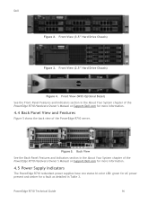
...) See the Front-Panel Features and Indicators section in the About Your System chapter of the PowerEdge R710 Hardware Owner's Manual on Support.Dell.com for a fault as detailed in the About Your System chapter of the PowerEdge R710 Hardware Owner's Manual on Support.Dell.com for more information. 4.5 Power Supply Indicators The PowerEdge R710 redundant power supplies have one status bi-color LED: green for...
...) See the Front-Panel Features and Indicators section in the About Your System chapter of the PowerEdge R710 Hardware Owner's Manual on Support.Dell.com for a fault as detailed in the About Your System chapter of the PowerEdge R710 Hardware Owner's Manual on Support.Dell.com for more information. 4.5 Power Supply Indicators The PowerEdge R710 redundant power supplies have one status bi-color LED: green for...
Technical Guide
Page 17
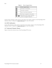
...-plugged/swapped) See the Power Indicator Codes section in the About Your System chapter of the PowerEdge R710 Hardware Owner's Manual on Support.Dell.com for more information. 4.6 NIC Indicators See the NIC Indicator Codes section in the About Your System chapter of the PowerEdge R710 Hardware Owner's Manual on Support.Dell.com for more information. 4.7 Internal Chassis Views Figure 6 shows the internal view...
...-plugged/swapped) See the Power Indicator Codes section in the About Your System chapter of the PowerEdge R710 Hardware Owner's Manual on Support.Dell.com for more information. 4.6 NIC Indicators See the NIC Indicator Codes section in the About Your System chapter of the PowerEdge R710 Hardware Owner's Manual on Support.Dell.com for more information. 4.7 Internal Chassis Views Figure 6 shows the internal view...
Technical Guide
Page 20
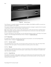
... the LCD panel, see the LCD Panel Features section in the About Your System chapter in the PowerEdge R710 Hardware Owner's Manual on Support.Dell.com. 4.11 Security For additional information regarding the following security features, see the PowerEdge R710 Hardware Owner's Manual on Support.Dell.com. 4.11.1 Cover Latch The PowerEdge R710 comes with the bezel present, but they cannot be used to protect...
... the LCD panel, see the LCD Panel Features section in the About Your System chapter in the PowerEdge R710 Hardware Owner's Manual on Support.Dell.com. 4.11 Security For additional information regarding the following security features, see the PowerEdge R710 Hardware Owner's Manual on Support.Dell.com. 4.11.1 Cover Latch The PowerEdge R710 comes with the bezel present, but they cannot be used to protect...
Technical Guide
Page 21
.... This mode includes the option to lock out the power and NMI switches on the control panel or set up a system password. 4.12 USB Key The port on Support.Dell.com. Some possible applications of custom logs or scratch pads for portable user defined information (not hot- The backplane storage...the Jumpers and Connectors chapter in the PowerEdge R710 Hardware Owner's Manual on the control panel is for an optional USB key and is mounted on the planar to provide backup power for the Real-Time Clock and CMOS RAM on the bezel secures the switch behind the bezel. Dell 4.11.4 TPM The TPM is ...
.... This mode includes the option to lock out the power and NMI switches on the control panel or set up a system password. 4.12 USB Key The port on Support.Dell.com. Some possible applications of custom logs or scratch pads for portable user defined information (not hot- The backplane storage...the Jumpers and Connectors chapter in the PowerEdge R710 Hardware Owner's Manual on the control panel is for an optional USB key and is mounted on the planar to provide backup power for the Real-Time Clock and CMOS RAM on the bezel secures the switch behind the bezel. Dell 4.11.4 TPM The TPM is ...
Technical Guide
Page 29
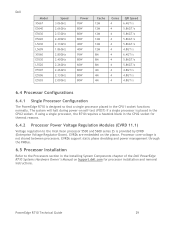
...and 5600 series 2S is placed in the Installing System Components chapter of the Dell PowerEdge R710 Systems Hardware Owner's Manual on Support.dell.com for processor installation and removal instructions. Dell Model X5667 E5640 E5630 E5620 L5630 L5609 X5560 E5530 ...5.86GT/s 4.8GT/s 4.8GT/s 4.8GT/s 6.4 Processor Configurations 6.4.1 Single Processor Configuration The PowerEdge R710 is not shared between processors. PowerEdge R710 Technical Guide 29 If using a single processor, the R710 requires a heatsink blank in the CPU2 socket for thermal reasons. 6.4.2 Processor Power Voltage ...
...and 5600 series 2S is placed in the Installing System Components chapter of the Dell PowerEdge R710 Systems Hardware Owner's Manual on Support.dell.com for processor installation and removal instructions. Dell Model X5667 E5640 E5630 E5620 L5630 L5609 X5560 E5530 ...5.86GT/s 4.8GT/s 4.8GT/s 4.8GT/s 6.4 Processor Configurations 6.4.1 Single Processor Configuration The PowerEdge R710 is not shared between processors. PowerEdge R710 Technical Guide 29 If using a single processor, the R710 requires a heatsink blank in the CPU2 socket for thermal reasons. 6.4.2 Processor Power Voltage ...
Technical Guide
Page 33
...) Mode In Advanced ECC (Lockstep) mode, the two channels closest to form one 128-bit channel. Additionally, correction of 1 GB memory modules per processor is possible in the Dell PowerEdge R710 Systems Hardware Owner's Manual on Support.dell.com. PowerEdge R710 Technical Guide 33 and x8based memory modules. This mode permits a larger total memory capacity but does not support SDDC with...
...) Mode In Advanced ECC (Lockstep) mode, the two channels closest to form one 128-bit channel. Additionally, correction of 1 GB memory modules per processor is possible in the Dell PowerEdge R710 Systems Hardware Owner's Manual on Support.dell.com. PowerEdge R710 Technical Guide 33 and x8based memory modules. This mode permits a larger total memory capacity but does not support SDDC with...
Technical Guide
Page 39
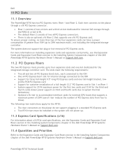
...System Components chapter of the Dell PowerEdge R710 Systems Hardware Owner's Manual on Support.dell.com. To ensure proper cooling, no more information on installing expansion cards and expansion-card priority, see the Expansion Cards and Expansion-Card Risers section in the Installing System Components chapter in the Dell PowerEdge R710 Systems Hardware Owner's Manual on Support.Dell... PCI Express card in the Installing System Components chapter of the Dell PowerEdge R710 Systems Hardware Owner's Manual on third and fourth cards due to system thermal limitations) Optional x16...
...System Components chapter of the Dell PowerEdge R710 Systems Hardware Owner's Manual on Support.dell.com. To ensure proper cooling, no more information on installing expansion cards and expansion-card priority, see the Expansion Cards and Expansion-Card Risers section in the Installing System Components chapter in the Dell PowerEdge R710 Systems Hardware Owner's Manual on Support.Dell... PCI Express card in the Installing System Components chapter of the Dell PowerEdge R710 Systems Hardware Owner's Manual on third and fourth cards due to system thermal limitations) Optional x16...
Technical Guide
Page 40
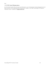
Dell 11.5 PCI Card Dimensions For information about PCIe slots and card dimensions, see the Expansion Cards and Expansion-Card Risers section in the Installing System Components chapter in the Dell PowerEdge R710 Systems Hardware Owner's Manual on Support.Dell.com. PowerEdge R710 Technical Guide 40
Dell 11.5 PCI Card Dimensions For information about PCIe slots and card dimensions, see the Expansion Cards and Expansion-Card Risers section in the Installing System Components chapter in the Dell PowerEdge R710 Systems Hardware Owner's Manual on Support.Dell.com. PowerEdge R710 Technical Guide 40
Technical Guide
Page 42
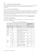
... the Hard-Drive Indicator Patterns section in the About Your System chapter in the Dell PowerEdge R710 Systems Hardware Owner's Manual on Support.Dell.com. 12.3 RAID Configurations See Table 11 for disk ... 3.5‖ = 6 2.5‖ = 2 3.5‖ = 2 2.5‖ = 8 3.5‖ = 6 2.5‖ = 8 3.5‖ = 6 2.5‖ = 8 3.5‖ = 6 PowerEdge R710 Technical Guide 42 For information on the backplane. The activity LED is still installed in the system. A 3.5‖ hard-drive backplane is driven by the storage enclosure processor (SEP) device on additional configurations, visit...
... the Hard-Drive Indicator Patterns section in the About Your System chapter in the Dell PowerEdge R710 Systems Hardware Owner's Manual on Support.Dell.com. 12.3 RAID Configurations See Table 11 for disk ... 3.5‖ = 6 2.5‖ = 2 3.5‖ = 2 2.5‖ = 8 3.5‖ = 6 2.5‖ = 8 3.5‖ = 6 2.5‖ = 8 3.5‖ = 6 PowerEdge R710 Technical Guide 42 For information on the backplane. The activity LED is still installed in the system. A 3.5‖ hard-drive backplane is driven by the storage enclosure processor (SEP) device on additional configurations, visit...
Information Update
Page 1
...voltage (low or standard), and system firmware/BIOS version. For systems with two processors: • Single-rank and dual-rank RDIMMs of sizes 2 GB, 4 GB, 8 GB, and 16 GB are supported for a total of up to 288 GB. • Quad-rank RDIMMs...GB. Two memory modules per channel support up to 1333 MHz. - One and two memory modules per channel are supported for a total of memory module speed. Dell PowerEdge R710-Information Update System Memory This document provides latest information on the supported memory configurations listed in the Hardware Owner's Manual at support.dell.com/manuals...
...voltage (low or standard), and system firmware/BIOS version. For systems with two processors: • Single-rank and dual-rank RDIMMs of sizes 2 GB, 4 GB, 8 GB, and 16 GB are supported for a total of up to 288 GB. • Quad-rank RDIMMs...GB. Two memory modules per channel support up to 1333 MHz. - One and two memory modules per channel are supported for a total of memory module speed. Dell PowerEdge R710-Information Update System Memory This document provides latest information on the supported memory configurations listed in the Hardware Owner's Manual at support.dell.com/manuals...


