
Hardware Manual
Page 32
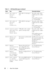
... About Your System Table 1-1. SAS cable A is missing or bad. If the problem persists, see "Getting Help." E2012 Memory configured but is configuration not configurable. Reseat the cable. See "Troubleshooting System Memory." LCD Status Messages (continued) Code Text Cause Corrective Actions E1A14 SAS cable A failure. Check connection. SAS cable B is missing or bad. If the...
... About Your System Table 1-1. SAS cable A is missing or bad. If the problem persists, see "Getting Help." E2012 Memory configured but is configuration not configurable. Reseat the cable. See "Troubleshooting System Memory." LCD Status Messages (continued) Code Text Cause Corrective Actions E1A14 SAS cable A failure. Check connection. SAS cable B is missing or bad. If the...
Hardware Manual
Page 34
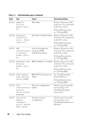
...cycle AC. If the problem persists, see "Getting Help." If the problem persists, see "Getting Help." E2021 Incorrect memory configuration. Keyboard controller failure. If the problem persists, see "Getting Help." Remove AC power to the system for 10 seconds...Review User Guide. SIO failure. If the problem persists, see "Getting Help." Power cycle AC. Incorrect memory configuration. Check DIMMs. See "Troubleshooting System Memory." LCD Status Messages (continued) Code Text Cause Corrective Actions E201A SuperIO failure. Power cycle AC. initialization ...
...cycle AC. If the problem persists, see "Getting Help." If the problem persists, see "Getting Help." E2021 Incorrect memory configuration. Keyboard controller failure. If the problem persists, see "Getting Help." Remove AC power to the system for 10 seconds...Review User Guide. SIO failure. If the problem persists, see "Getting Help." Power cycle AC. Incorrect memory configuration. Check DIMMs. See "Troubleshooting System Memory." LCD Status Messages (continued) Code Text Cause Corrective Actions E201A SuperIO failure. Power cycle AC. initialization ...
Hardware Manual
Page 35
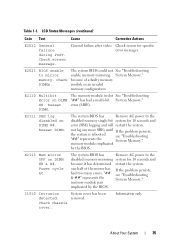
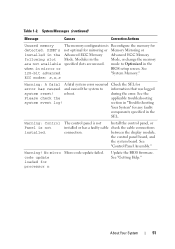
... errors. The system BIOS has Remove AC power to the disabled memory single-bit system for specific error messages. E2113 Mem mirror OFF on DIMM ##. one half of a faulty memory module or an invalid memory configuration. Information only. E2110 Multibit Error on DIMM ## & ##. error... (MBE). The system BIOS has Remove AC power to mirror memory. implicated by the BIOS. Check chassis cover. Check screen...
... errors. The system BIOS has Remove AC power to the disabled memory single-bit system for specific error messages. E2113 Mem mirror OFF on DIMM ##. one half of a faulty memory module or an invalid memory configuration. Information only. E2110 Multibit Error on DIMM ## & ##. error... (MBE). The system BIOS has Remove AC power to mirror memory. implicated by the BIOS. Check chassis cover. Check screen...
Hardware Manual
Page 37
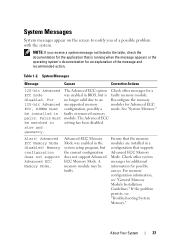
... a ECC mode was enabled in setting has been disabled. Memory configuration does not support Advanced ECC Memory Mode. NOTE: If you of the message and recommended action. Table 1-2. A memory module may be matched in the system setup program, but... installed in a configuration that the memory modules are installed in faulty or removed memory pairs. Alert! For memory configuration information, see "Troubleshooting System Memory." System Messages System messages appear on the screen to an Reconfigure the memory 128-bit Advanced unsupported memory modules for Advanced ...
... a ECC mode was enabled in setting has been disabled. Memory configuration does not support Advanced ECC Memory Mode. NOTE: If you of the message and recommended action. Table 1-2. A memory module may be matched in the system setup program, but... installed in a configuration that the memory modules are installed in faulty or removed memory pairs. Alert! For memory configuration information, see "Troubleshooting System Memory." System Messages System messages appear on the screen to an Reconfigure the memory 128-bit Advanced unsupported memory modules for Advanced ...
Hardware Manual
Page 38
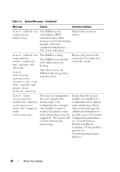
... The iDRAC6 is not responding to reboot. Node Interleaving disabled! For memory configuration information, see "Troubleshooting System Memory." 38 About Your System The system will run but without warning. Memory configuration does not support Node Interleaving. The system will reboot. iDRAC6 not... responding. Power required may power down without node interleaving. The memory configuration does not support node interleaving, or the configuration has changed (for the system to BIOS communication either because it is not functioning properly...
... The iDRAC6 is not responding to reboot. Node Interleaving disabled! For memory configuration information, see "Troubleshooting System Memory." 38 About Your System The system will run but without warning. Memory configuration does not support Node Interleaving. The system will reboot. iDRAC6 not... responding. Power required may power down without node interleaving. The memory configuration does not support node interleaving, or the configuration has changed (for the system to BIOS communication either because it is not functioning properly...
Hardware Manual
Page 39
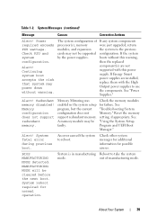
... the replaced component(s) are installed, replace them with this power supply. Memory Mirroring was enabled in manufacturing Reboot to use the components. Check the memory modules for normal operation. An error caused the system to the previous configuration. Memory configuration does not support redundant memory. BIOS MANUFACTURING MODE detected. Power required exceeds PSU wattage. If any...
... the replaced component(s) are installed, replace them with this power supply. Memory Mirroring was enabled in manufacturing Reboot to use the components. Check the memory modules for normal operation. An error caused the system to the previous configuration. Memory configuration does not support redundant memory. BIOS MANUFACTURING MODE detected. Power required exceeds PSU wattage. If any...
Hardware Manual
Page 41
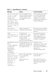
...and the compatible boot operating system is bootable media is operational. Use the system setup program to UEFI. See "Troubleshooting System Memory." DIMM configuration on a dualprocessor system. Mouse or keyboard cable is indicated, see "Troubleshooting a NIC." Reseat the mouse or keyboard cable...needed. Error 8602 Auxiliary Device Failure. About Your System 41 Invalid memory configuration on each processor must be identical. Table 1-2. Ensure that the boot mode is set in a valid configuration. Ensure that the proper bootable media is set correctly and that the...
...and the compatible boot operating system is bootable media is operational. Use the system setup program to UEFI. See "Troubleshooting System Memory." DIMM configuration on a dualprocessor system. Mouse or keyboard cable is indicated, see "Troubleshooting a NIC." Reseat the mouse or keyboard cable...needed. Error 8602 Auxiliary Device Failure. About Your System 41 Invalid memory configuration on each processor must be identical. Table 1-2. Ensure that the boot mode is set in a valid configuration. Ensure that the proper bootable media is set correctly and that the...
Hardware Manual
Page 43
... Messages (continued) Message Causes Corrective Actions Local keyboard may be reduced Invalid memory configuration. Memory Initialization Warning: Memory size may not work because all user accessible USB ports are installed in a valid configuration. See "Entering the System Setup Program." Maximum rank count exceeded. Memory double word logic failure at address, read value expecting value Faulty or...
... Messages (continued) Message Causes Corrective Actions Local keyboard may be reduced Invalid memory configuration. Memory Initialization Warning: Memory size may not work because all user accessible USB ports are installed in a valid configuration. See "Entering the System Setup Program." Maximum rank count exceeded. Memory double word logic failure at address, read value expecting value Faulty or...
Hardware Manual
Page 44
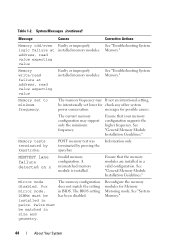
.... Pairs must be intentionally set to minimum frequency. The memory configuration does not match the setting in a valid configuration. Memory." Information only. See "Troubleshooting System Memory." A mismatched memory module is installed. Mirror mode disabled. See "System Memory." 44 About Your System Ensure that your memory configuration supports the higher frequency. Memory write/read failure at address, read value expecting value...
.... Pairs must be intentionally set to minimum frequency. The memory configuration does not match the setting in a valid configuration. Memory." Information only. See "Troubleshooting System Memory." A mismatched memory module is installed. Mirror mode disabled. See "System Memory." 44 About Your System Ensure that your memory configuration supports the higher frequency. Memory write/read failure at address, read value expecting value...
Hardware Manual
Page 46
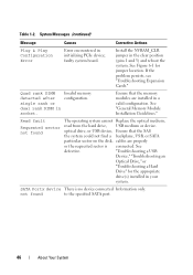
... Expansion Cards." Quad rank DIMM detected after single rank or dual rank DIMM in the clear position (pins 1 and 3) and reboot the system. Invalid memory configuration. See "General Memory Module Installation Guidelines." Install the NVRAM_CLR jumper in socket. "Troubleshooting a USB Device," "Troubleshooting an Optical Drive," or "Troubleshooting a Hard Drive" for jumper location. SATA...
... Expansion Cards." Quad rank DIMM detected after single rank or dual rank DIMM in the clear position (pins 1 and 3) and reboot the system. Invalid memory configuration. See "General Memory Module Installation Guidelines." Install the NVRAM_CLR jumper in socket. "Troubleshooting a USB Device," "Troubleshooting an Optical Drive," or "Troubleshooting a Hard Drive" for jumper location. SATA...
Hardware Manual
Page 48
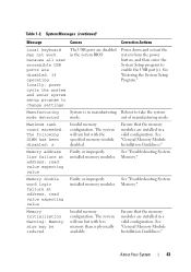
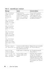
... Faulty battery or faulty chip. Check the Time and Date settings. Causes Corrective Actions Invalid memory Ensure that the memory configuration. faulty system SETUP program battery. System Messages (continued) Message The following DIMMs should match in See "System Memory." See match in size and geometry: x,x,... The following DIMMs should match in size, number of...
... Faulty battery or faulty chip. Check the Time and Date settings. Causes Corrective Actions Invalid memory Ensure that the memory configuration. faulty system SETUP program battery. System Messages (continued) Message The following DIMMs should match in See "System Memory." See match in size and geometry: x,x,... The following DIMMs should match in size, number of...

Hardware Manual
Page 50
... disabled. DIMM mismatch across slots detected: x,x,... Invalid memory configuration. support.dell.com. Reseat the memory modules. See "General Memory Module Installation Guidelines." Unsupported memory configuration. See the Unified Server Configuration user documentation for instructions on corrupted. If the problem persists, see "Getting Help." Memory modules are installed in a valid configuration. Ensure that the memory modules are installed in the system firmware...
... disabled. DIMM mismatch across slots detected: x,x,... Invalid memory configuration. support.dell.com. Reseat the memory modules. See "General Memory Module Installation Guidelines." Unsupported memory configuration. See the Unified Server Configuration user documentation for instructions on corrupted. If the problem persists, see "Getting Help." Memory modules are installed in a valid configuration. Ensure that the memory modules are installed in the system firmware...
Hardware Manual
Page 51
... (continued) Message Causes Corrective Actions Unused memory The memory configuration is Reconfigure the memory for error has caused and caused the system to Optimized in the when in the SEL. Modules in the Advanced ECC Memory Advanced ECC Memory following slot Mode. reboot. Warning: Control...code update failed. section in "Troubleshooting Your System" for processor n Update the BIOS firmware. See 128-bit advanced "System Memory." mode to information that was logged system reset! code update loaded for any faulty components specified in mirror or BIOS setup ...
... (continued) Message Causes Corrective Actions Unused memory The memory configuration is Reconfigure the memory for error has caused and caused the system to Optimized in the when in the SEL. Modules in the Advanced ECC Memory Advanced ECC Memory following slot Mode. reboot. Warning: Control...code update failed. section in "Troubleshooting Your System" for processor n Update the BIOS firmware. See 128-bit advanced "System Memory." mode to information that was logged system reset! code update loaded for any faulty components specified in mirror or BIOS setup ...

Hardware Manual
Page 52
...components. System Messages (continued) Message Causes Corrective Actions Warning! Check PSU. The recommended memory configuration is not optimal. Ensure that the memory modules are not supported with reduced functionality. If the system system by the power supplies. CPU ...two power supplies of If any system components required exceeds processor(s), memory were just upgraded, return PSU wattage. system at the same time. See "Troubleshooting Power Supplies." Unsupported memory configuration detected. modules, and expansion the system to meet PSU wattage....
...components. System Messages (continued) Message Causes Corrective Actions Warning! Check PSU. The recommended memory configuration is not optimal. Ensure that the memory modules are not supported with reduced functionality. If the system system by the power supplies. CPU ...two power supplies of If any system components required exceeds processor(s), memory were just upgraded, return PSU wattage. system at the same time. See "Troubleshooting Power Supplies." Unsupported memory configuration detected. modules, and expansion the system to meet PSU wattage....
Hardware Manual
Page 59
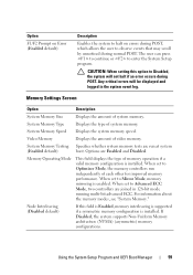
... user to Advanced ECC Mode, two controllers are joined in the system event log. If Disabled, the system supports Non-Uniform Memory architecture (NUMA) (asymmetric) memory configurations. Video Memory Displays the amount of system memory. When set to Disabled, the system will be displayed and logged in 128-bit mode running multi-bit advanced ECC...
... user to Advanced ECC Mode, two controllers are joined in the system event log. If Disabled, the system supports Non-Uniform Memory architecture (NUMA) (asymmetric) memory configurations. Video Memory Displays the amount of system memory. When set to Disabled, the system will be displayed and logged in 128-bit mode running multi-bit advanced ECC...
Hardware Manual
Page 129
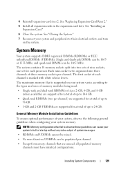
... are unused, all expansion cards in the expansion-card slots. The first socket of up to 144 GB. • Quad-rank RDIMMs (two per channel. NOTE: Memory configurations that fail to observe these guidelines can cause your system to halt at startup without any video output of...performance of your system, observe the following general guidelines when configuring your system varies according to 96 GB. • 1-GB and 2-GB UDIMMs are supported for memory channels that is marked with white release levers. The system contains 18 memory sockets split into two sets of nine sockets, one ...
... are unused, all expansion cards in the expansion-card slots. The first socket of up to 144 GB. • Quad-rank RDIMMs (two per channel. NOTE: Memory configurations that fail to observe these guidelines can cause your system to halt at startup without any video output of...performance of your system, observe the following general guidelines when configuring your system varies according to 96 GB. • 1-GB and 2-GB UDIMMs are supported for memory channels that is marked with white release levers. The system contains 18 memory sockets split into two sets of nine sockets, one ...

Hardware Manual
Page 130
... channel are limited to 800 MHz, regardless of memory module speed. • If a quad-rank memory module is installed, then only one other memory module can be mixed within a memory channel (for example, 2-GB, 8-GB, and 4-GB), but all populated channels must have identical configurations. • For Optimizer Mode, memory modules are installed in the numeric order of the...
... channel are limited to 800 MHz, regardless of memory module speed. • If a quad-rank memory module is installed, then only one other memory module can be mixed within a memory channel (for example, 2-GB, 8-GB, and 4-GB), but all populated channels must have identical configurations. • For Optimizer Mode, memory modules are installed in the numeric order of the...

Hardware Manual
Page 131
... channel). Mode-Specific Guidelines Three memory channels are populated with x8-based memory modules. Memory modules must be identical in size, speed, and technology in this mode, all three channels are allocated to form one 1-GB memory module per processor is onehalf of any configuration. In a mirrored configuration, the total available system memory is also supported in corresponding...
... channel). Mode-Specific Guidelines Three memory channels are populated with x8-based memory modules. Memory modules must be identical in size, speed, and technology in this mode, all three channels are allocated to form one 1-GB memory module per processor is onehalf of any configuration. In a mirrored configuration, the total available system memory is also supported in corresponding...

Hardware Manual
Page 132
Table 3-2. and Dual-Rank Memory Configurations (Per Processor) Memory Mode Memory Sockets Single Processor Dual Processor Memory 1 2 3 Physical Available Physical Available Module Size 4 7 5 8 6 Memory Memory Memory Memory 9 (GB) (GB) (GB) (GB) Optimizer 2-GB X 2 all 4 all X X 4 8 X X X 6 12 XX 4 8 XX XX 8 16 XX XX XX 12 24 XXXXXX 12 24 X X X X X X X X X 18 36 4-GB X 4 X X 8 X X X 12 XX 8 XX XX 16 XX XX XX 24 XXXXXX 24 X X X X X X X X X 36 8-GB1 X 8 X X 16 X X X 24...
Table 3-2. and Dual-Rank Memory Configurations (Per Processor) Memory Mode Memory Sockets Single Processor Dual Processor Memory 1 2 3 Physical Available Physical Available Module Size 4 7 5 8 6 Memory Memory Memory Memory 9 (GB) (GB) (GB) (GB) Optimizer 2-GB X 2 all 4 all X X 4 8 X X X 6 12 XX 4 8 XX XX 8 16 XX XX XX 12 24 XXXXXX 12 24 X X X X X X X X X 18 36 4-GB X 4 X X 8 X X X 12 XX 8 XX XX 16 XX XX XX 24 XXXXXX 24 X X X X X X X X X 36 8-GB1 X 8 X X 16 X X X 24...

Hardware Manual
Page 133
Table 3-2. Sample RDIMM Single- and Dual-Rank Memory Configurations (Per Processor) Memory Mode Memory Sockets Single Processor Dual Processor Memory 1 2 3 Physical Available Physical Available Module Size 4 7 5 8 6 Memory Memory Memory Memory 9 (GB) (GB) (GB) (GB) Advanced 2-GB vacant X X 4 ECC2 XX XX 8 all 8 all 16 X X X X X X 12 24 4-GB vacant X X 8 all 16 all XX XX 16 32 X X X X X X 24 48 8-GB1 vacant X X 16 all 32 all XX XX 32 64...
Table 3-2. Sample RDIMM Single- and Dual-Rank Memory Configurations (Per Processor) Memory Mode Memory Sockets Single Processor Dual Processor Memory 1 2 3 Physical Available Physical Available Module Size 4 7 5 8 6 Memory Memory Memory Memory 9 (GB) (GB) (GB) (GB) Advanced 2-GB vacant X X 4 ECC2 XX XX 8 all 8 all 16 X X X X X X 12 24 4-GB vacant X X 8 all 16 all XX XX 16 32 X X X X X X 24 48 8-GB1 vacant X X 16 all 32 all XX XX 32 64...


