
Hardware Manual
Page 4
... Boot Manager 55 Choosing the System Boot Mode 55 Entering the System Setup Program 56 Responding to Error Messages 56 Using the System Setup Program Navigation Keys 56 System Setup Options 57 Main Screen 57 Memory Settings Screen 59 Processor Settings Screen 60 SATA Settings Screen 60 Boot Settings Screen 61 Integrated... Boot Settings Screen 69 System Utilities Screen 69 System and Setup Password Features 70 Using the System Password 70 Using the Setup Password 72 iDRAC Configuration Utility 73 4 Contents
... Boot Manager 55 Choosing the System Boot Mode 55 Entering the System Setup Program 56 Responding to Error Messages 56 Using the System Setup Program Navigation Keys 56 System Setup Options 57 Main Screen 57 Memory Settings Screen 59 Processor Settings Screen 60 SATA Settings Screen 60 Boot Settings Screen 61 Integrated... Boot Settings Screen 69 System Utilities Screen 69 System and Setup Password Features 70 Using the System Password 70 Using the Setup Password 72 iDRAC Configuration Utility 73 4 Contents
Hardware Manual
Page 32
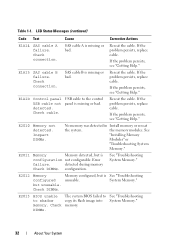
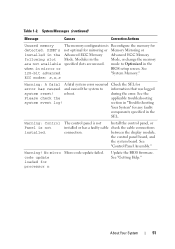
... missing or bad. E2010 Memory not detected. Error failure. Check DIMMs. The system BIOS failed to shadow memory. Check connection. If the problem persists, replace cable. If the problem persists, see "Getting Help." Inspect DIMMs. No memory was detected in Install memory or reseat the system. Check DIMMs. Memory configured, but is configuration not configurable. If the problem persists...
... missing or bad. E2010 Memory not detected. Error failure. Check DIMMs. The system BIOS failed to shadow memory. Check connection. If the problem persists, replace cable. If the problem persists, see "Getting Help." Inspect DIMMs. No memory was detected in Install memory or reseat the system. Check DIMMs. Memory configured, but is configuration not configurable. If the problem persists...
Hardware Manual
Page 34
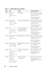
Power cycle AC. E201B Keyboard Controller error. Remove AC power to the system for specific error messages. BIOS shutdown test failure. Check screen message. See "Troubleshooting System Memory". 34 About Your System SIO failure. If the problem persists, see "Getting Help." E201D Shutdown test failure. failure. E2021 Incorrect memory configuration. Review User Guide. Power cycle AC...
Power cycle AC. E201B Keyboard Controller error. Remove AC power to the system for specific error messages. BIOS shutdown test failure. Check screen message. See "Troubleshooting System Memory". 34 About Your System SIO failure. If the problem persists, see "Getting Help." E201D Shutdown test failure. failure. E2021 Incorrect memory configuration. Review User Guide. Power cycle AC...
Hardware Manual
Page 35
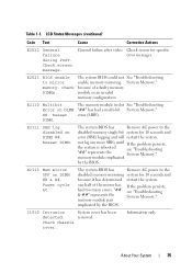
... DIMM. Reseat DIMM. Check chassis cover. because of the mirror has had a multi-bit System Memory." error (MBE). E2111 SBE log disabled on DIMM ##. memory module implicated by the BIOS. one half of a faulty memory module or an invalid memory configuration. System cover has been removed. Check DIMMs. The system BIOS could not See "Troubleshooting enable...
... DIMM. Reseat DIMM. Check chassis cover. because of the mirror has had a multi-bit System Memory." error (MBE). E2111 SBE log disabled on DIMM ##. memory module implicated by the BIOS. one half of a faulty memory module or an invalid memory configuration. System cover has been removed. Check DIMMs. The system BIOS could not See "Troubleshooting enable...
Hardware Manual
Page 39
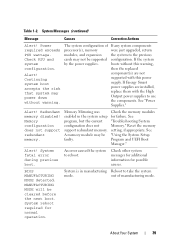
... the system setup program, but the current configuration does not support redundant memory. About Your System 39 Reset the memory setting, if appropriate. An error caused the system to take the system mode. out of processor(s), memory modules, and expansion cards may be faulty....without warning. MANUFACTURING MODE will be supported by the power supplies. Alert! Alert! System fatal error during previous boot. The system configuration of manufacturing mode. A memory module may not be cleared before the next boot. Continuing system boot accepts the risk that system...
... the system setup program, but the current configuration does not support redundant memory. About Your System 39 Reset the memory setting, if appropriate. An error caused the system to take the system mode. out of processor(s), memory modules, and expansion cards may be faulty....without warning. MANUFACTURING MODE will be supported by the power supplies. Alert! Alert! System fatal error during previous boot. The system configuration of manufacturing mode. A memory module may not be cleared before the next boot. Continuing system boot accepts the risk that system...
Hardware Manual
Page 41
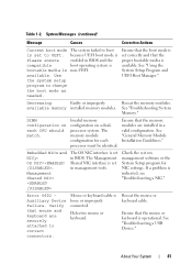
... NIC=, Management Shared NIC= The OS NIC interface is indicated, see "Troubleshooting a NIC." Error 8602 Auxiliary Device Failure. See "Troubleshooting a USB Device." Ensure that the memory modules are securely attached to change the boot mode as needed. Invalid memory configuration on each processor must be identical. Ensure that the boot mode is set to...
... NIC=, Management Shared NIC= The OS NIC interface is indicated, see "Troubleshooting a NIC." Error 8602 Auxiliary Device Failure. See "Troubleshooting a USB Device." Ensure that the memory modules are securely attached to change the boot mode as needed. Invalid memory configuration on each processor must be identical. Ensure that the boot mode is set to...
Hardware Manual
Page 46
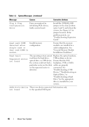
...Configuration Error Error encountered in socket. faulty system board. Quad rank DIMM detected after single rank or dual rank DIMM in initializing PCIe device; See defective. "Troubleshooting a USB Device," "Troubleshooting an Optical Drive," or "Troubleshooting a Hard Drive" for jumper location. Invalid memory configuration.... optical drive, or USB device, Ensure that the memory modules are properly or the requested sector is no device connected Information only....
...Configuration Error Error encountered in socket. faulty system board. Quad rank DIMM detected after single rank or dual rank DIMM in initializing PCIe device; See defective. "Troubleshooting a USB Device," "Troubleshooting an Optical Drive," or "Troubleshooting a Hard Drive" for jumper location. Invalid memory configuration.... optical drive, or USB device, Ensure that the memory modules are properly or the requested sector is no device connected Information only....
Hardware Manual
Page 47
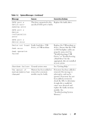
... detected and replace the faulty memory module. Shutdown failure General system error. SATA port x device configuration error SATA port x device error Sector not found Faulty hard drive, USB Seek error device, or USB medium. The amount of Memory has been added or system memory has removed or a memory changed module may be ignored. If memory has been added or removed...
... detected and replace the faulty memory module. Shutdown failure General system error. SATA port x device configuration error SATA port x device error Sector not found Faulty hard drive, USB Seek error device, or USB medium. The amount of Memory has been added or system memory has removed or a memory changed module may be ignored. If memory has been added or removed...
Hardware Manual
Page 51
... Message Causes Corrective Actions Unused memory The memory configuration is Reconfigure the memory for error has caused and caused the system to Optimized in the when in the Advanced ECC Memory Advanced ECC Memory following slot Mode. ECC modes: x,x,x Warning: A fatal A fatal system error occurred Check the SEL for .... Warning! See "Getting Help." About Your System 51 DIMM's not optimal for mirroring or Memory Mirroring or installed in mirror or BIOS setup screen. during the error. Warning: Control Panel is not Install the control panel, or installed or has a faulty ...
... Message Causes Corrective Actions Unused memory The memory configuration is Reconfigure the memory for error has caused and caused the system to Optimized in the when in the Advanced ECC Memory Advanced ECC Memory following slot Mode. ECC modes: x,x,x Warning: A fatal A fatal system error occurred Check the SEL for .... Warning! See "Getting Help." About Your System 51 DIMM's not optimal for mirroring or Memory Mirroring or installed in mirror or BIOS setup screen. during the error. Warning: Control Panel is not Install the control panel, or installed or has a faulty ...
Hardware Manual
Page 58
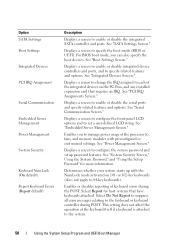
... 58 Using the System Setup Program and UEFI Boot Manager This setting does not affect the operation of keyboard errors during POST. See "SATA Settings Screen." Displays a screen to configure the front-panel LCD options and to 84-key keyboards). Enables you can also specify the boot devices....assigned to manage power usage of the integrated devices on 101- For BIOS boot mode, you to each of the processor(s), fans, and memory modules with the NumLock mode activated on the PCI bus, and any installed expansion card that have keyboards attached. See "Serial Communication Screen...
... 58 Using the System Setup Program and UEFI Boot Manager This setting does not affect the operation of keyboard errors during POST. See "SATA Settings Screen." Displays a screen to configure the front-panel LCD options and to 84-key keyboards). Enables you can also specify the boot devices....assigned to manage power usage of the integrated devices on 101- For BIOS boot mode, you to each of the processor(s), fans, and memory modules with the NumLock mode activated on the PCI bus, and any installed expansion card that have keyboards attached. See "Serial Communication Screen...
Hardware Manual
Page 59
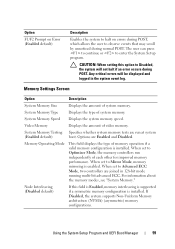
... critical errors will not halt if an error occurs during normal POST. System Memory Testing Specifies whether system memory tests are Enabled and Disabled. When set to Mirror Mode, memory mirroring is enabled. Memory Operating Mode This field displays the type of video memory. CAUTION: When setting this field is Enabled, memory interleaving is supported if a symmetric memory configuration is...
... critical errors will not halt if an error occurs during normal POST. System Memory Testing Specifies whether system memory tests are Enabled and Disabled. When set to Mirror Mode, memory mirroring is enabled. Memory Operating Mode This field displays the type of video memory. CAUTION: When setting this field is Enabled, memory interleaving is supported if a symmetric memory configuration is...

Hardware Manual
Page 161
...Dell™ PowerEdge™ Diagnostics." Go to step 14 if an error message appears indicating a fault with all applicable guidelines. 1 If the system is operational, run the appropriate online diagnostic test. See "Opening the System." 7 Remove the cooling shroud. See "Installing the Cooling Shroud." 11 Close the system. See "Memory... Memory Modules." 10 Replace the cooling shroud. See "General Memory Module Installation Guidelines." 9 Reseat the memory modules in their sockets. NOTE: Invalid memory configurations can cause your memory configuration complies with a specific memory ...
...Dell™ PowerEdge™ Diagnostics." Go to step 14 if an error message appears indicating a fault with all applicable guidelines. 1 If the system is operational, run the appropriate online diagnostic test. See "Opening the System." 7 Remove the cooling shroud. See "Installing the Cooling Shroud." 11 Close the system. See "Memory... Memory Modules." 10 Replace the cooling shroud. See "General Memory Module Installation Guidelines." 9 Reseat the memory modules in their sockets. NOTE: Invalid memory configurations can cause your memory configuration complies with a specific memory ...
Hardware Manual
Page 192
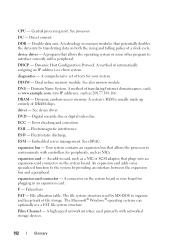
... devices. 192 Glossary The file system structure used primarily with a peripheral. Dynamic Host Configuration Protocol. A method of file storage. A connector on the system board. A high...Error checking and correction. Digital versatile disc or digital video disc. ESD - F - The Microsoft® Windows® operating systems can optionally use a FAT file system structure. DC - Dual in memory modules that potentially doubles the data rate by providing an interface between the expansion bus and a peripheral. expansion-card connector - A system's RAM...
... devices. 192 Glossary The file system structure used primarily with a peripheral. Dynamic Host Configuration Protocol. A method of file storage. A connector on the system board. A high...Error checking and correction. Digital versatile disc or digital video disc. ESD - F - The Microsoft® Windows® operating systems can optionally use a FAT file system structure. DC - Dual in memory modules that potentially doubles the data rate by providing an interface between the expansion bus and a peripheral. expansion-card connector - A system's RAM...
Hardware Manual
Page 195
...maintaining the date, time, and system configuration information. An improved PCI expansion bus technology that are optimized to a network. A portable flash memory storage device integrated with the format command... of a set of physical drives stores data and one of memory, such as integrated memory (ROM and RAM) and add-in your system. When applied to interface between ...or system memory. Nanosecond(s). Memory that one or more sets of additional drives stores duplicate copies of data redundancy applicable to signal the processor about hardware errors. An area in memory modules (...
...maintaining the date, time, and system configuration information. An improved PCI expansion bus technology that are optimized to a network. A portable flash memory storage device integrated with the format command... of a set of physical drives stores data and one of memory, such as integrated memory (ROM and RAM) and add-in your system. When applied to interface between ...or system memory. Nanosecond(s). Memory that one or more sets of additional drives stores duplicate copies of data redundancy applicable to signal the processor about hardware errors. An area in memory modules (...
Hardware Manual
Page 197
... Single device data correction. Allows hard drives to report errors and failures to the system BIOS and then display an error message on each disk used by a "stripe" is... an array, but only uses a portion of disks in effect until you call Dell for operation. A virtual disk may use several stripes on the system used to...memory card. Disk striping writes data across three or more processors connected via a high-bandwidth link and managed by setting features such as the processor(s), RAM, controllers for peripherals, and various ROM chips. Serial-attached SCSI. system configuration...
... Single device data correction. Allows hard drives to report errors and failures to the system BIOS and then display an error message on each disk used by a "stripe" is... an array, but only uses a portion of disks in effect until you call Dell for operation. A virtual disk may use several stripes on the system used to...memory card. Disk striping writes data across three or more processors connected via a high-bandwidth link and managed by setting features such as the processor(s), RAM, controllers for peripherals, and various ROM chips. Serial-attached SCSI. system configuration...
Hardware Manual
Page 204
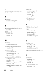
...-on-motherboard (LOM) See NICs. LCD panel features, 15 menus, 16 M memory troubleshooting, 160 Memory Mirroring memory mode, 131 memory mode Advanced ECC, 131 Memory Mirroring, 131 Optimizer, 131 memory modules (DIMMs) configuring, 129 installing, 134 RDIMM configurations, 132 removing, 136 UDIMM configurations, 120, 134 204 Index messages error messages, 56 status LCD, 23 system, 37 warning, 53 microprocessor See...
...-on-motherboard (LOM) See NICs. LCD panel features, 15 menus, 16 M memory troubleshooting, 160 Memory Mirroring memory mode, 131 memory mode Advanced ECC, 131 Memory Mirroring, 131 Optimizer, 131 memory modules (DIMMs) configuring, 129 installing, 134 RDIMM configurations, 132 removing, 136 UDIMM configurations, 120, 134 204 Index messages error messages, 56 status LCD, 23 system, 37 warning, 53 microprocessor See...
Technical Guide
Page 30
Key features of the R710 memory system include the following configurations: Three channels per channel. o This mode offers the most DIMM population flexibility and system memory capacity, but offers the least number of UDIMM memory (twelve 2 GB UDIMMs) Support for 1066/1333 MHz single- PowerEdge R710 Technical Guide 30 o Memory modules are not accessed (DIMMs enter a low power...
Key features of the R710 memory system include the following configurations: Three channels per channel. o This mode offers the most DIMM population flexibility and system memory capacity, but offers the least number of UDIMM memory (twelve 2 GB UDIMMs) Support for 1066/1333 MHz single- PowerEdge R710 Technical Guide 30 o Memory modules are not accessed (DIMMs enter a low power...
Technical Guide
Page 33
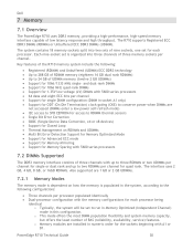
...-bit correction and multi-bit error detection. A minimal single-channel configuration of a x4 or x8 device failure is also supported in this mode. 7.11 Supported Configurations See the System Memory section in the Installing System Components chapter in the Dell PowerEdge R710 Systems Hardware Owner's Manual on Support.dell.com. Correction of 1 GB memory modules per processor is also possible...
...-bit correction and multi-bit error detection. A minimal single-channel configuration of a x4 or x8 device failure is also supported in this mode. 7.11 Supported Configurations See the System Memory section in the Installing System Components chapter in the Dell PowerEdge R710 Systems Hardware Owner's Manual on Support.dell.com. Correction of 1 GB memory modules per processor is also possible...
Technical Guide
Page 36
...61623; Memory mirroring support SETUP access through four split segments. PowerEdge R710 Technical Guide 36 The R710 supports all of POST USB 2.0 (USB boot code is 1.1 compliant) F1/F2 error logging ...Dell BIOS core, supporting the following features: Intel® Xeon® 5500 and 5600 processor series 2S support Simultaneous Multi-Threading (SMT) support Processor Turbo Mode support PCI 2.3 compliant Plug and Play 1.0a compliant MP (Multiprocessor) 1.4 compliant Ability to direct configuration...
...61623; Memory mirroring support SETUP access through four split segments. PowerEdge R710 Technical Guide 36 The R710 supports all of POST USB 2.0 (USB boot code is 1.1 compliant) F1/F2 error logging ...Dell BIOS core, supporting the following features: Intel® Xeon® 5500 and 5600 processor series 2S support Simultaneous Multi-Threading (SMT) support Processor Turbo Mode support PCI 2.3 compliant Plug and Play 1.0a compliant MP (Multiprocessor) 1.4 compliant Ability to direct configuration...


