
Hardware Manual
Page 13
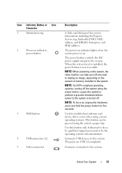
.... About Your System 13 The power button controls the DC power supply output to display an image, depending on . Used to troubleshoot software and device driver errors when using certain operating systems. This button can take up to 25 seconds to the system. The power-on indicator lights when the system...
.... About Your System 13 The power button controls the DC power supply output to display an image, depending on . Used to troubleshoot software and device driver errors when using certain operating systems. This button can take up to 25 seconds to the system. The power-on indicator lights when the system...
Hardware Manual
Page 62
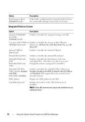
... has failed to boot, the system will reattempt to boot from the network. Capability Detected Displays the features of an additional driver. 62 Using the System Setup Program and UEFI Boot Manager Integrated Devices Screen Option Description Integrated SAS/RAID Controller (Enabled default)... Only Back Ports On, and All Ports Off. NOTE: Some NIC features may also be accessed through the system's management controller.) Embedded Gb NICx (NIC1 default: Enabled with iSCSI Boot, and Disabled. Other NICs: Enabled) Enables or disables the embedded NICs. Internal USB Port ...
... has failed to boot, the system will reattempt to boot from the network. Capability Detected Displays the features of an additional driver. 62 Using the System Setup Program and UEFI Boot Manager Integrated Devices Screen Option Description Integrated SAS/RAID Controller (Enabled default)... Only Back Ports On, and All Ports Off. NOTE: Some NIC features may also be accessed through the system's management controller.) Embedded Gb NICx (NIC1 default: Enabled with iSCSI Boot, and Disabled. Other NICs: Enabled) Enables or disables the embedded NICs. Internal USB Port ...
Hardware Manual
Page 75
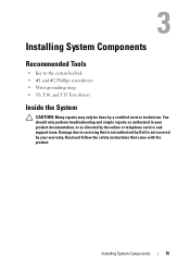
.... Damage due to the system keylock • #1 and #2 Phillips screwdrivers • Wrist grounding strap • T8, T10, and T15 Torx drivers Inside the System CAUTION: Many repairs may only be done by a certified service technician. Read and follow the safety instructions that is not authorized by... Dell is not covered by the online or telephone service and support team. You should only perform troubleshooting and simple repairs as directed by...
.... Damage due to the system keylock • #1 and #2 Phillips screwdrivers • Wrist grounding strap • T8, T10, and T15 Torx drivers Inside the System CAUTION: Many repairs may only be done by a certified service technician. Read and follow the safety instructions that is not authorized by... Dell is not covered by the online or telephone service and support team. You should only perform troubleshooting and simple repairs as directed by...
Hardware Manual
Page 143
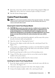
.... 2 Open the system. See Figure 3-34. 5 Bend the panel upward to allow access to the mounting screws. 6 Using a T10 Torx driver, remove the two screws that secure the display module to remove and install either module. Use the following instructions to the system chassis. 7 Remove ... and re-enter any customized option settings as directed by a certified service technician. Read and follow the safety instructions that is not authorized by Dell is not covered by your product documentation, or as needed. 12 Exit the System Setup program. See Figure 3-34. 4 Using a knife or...
.... 2 Open the system. See Figure 3-34. 5 Bend the panel upward to allow access to the mounting screws. 6 Using a T10 Torx driver, remove the two screws that secure the display module to remove and install either module. Use the following instructions to the system chassis. 7 Remove ... and re-enter any customized option settings as directed by a certified service technician. Read and follow the safety instructions that is not authorized by Dell is not covered by your product documentation, or as needed. 12 Exit the System Setup program. See Figure 3-34. 4 Using a knife or...
Hardware Manual
Page 145
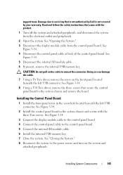
... control panel cable at back of the control panel board. CAUTION: Do not pull on the cable to servicing that is not authorized by Dell is not covered by your warranty. Read and follow the safety instructions that secure the control panel board to the power source and turn on... and attached peripherals, and disconnect the system from the control panel board. Damage due to unseat the connector. See Figure 3-34. 8 Using a T10 Torx driver, remove the three screws that came with the three Torx screws. See "Closing the System." 8 Reconnect the system to the system chassis and remove the...
... control panel cable at back of the control panel board. CAUTION: Do not pull on the cable to servicing that is not authorized by Dell is not covered by your warranty. Read and follow the safety instructions that secure the control panel board to the power source and turn on... and attached peripherals, and disconnect the system from the control panel board. Damage due to unseat the connector. See Figure 3-34. 8 Using a T10 Torx driver, remove the three screws that came with the three Torx screws. See "Closing the System." 8 Reconnect the system to the system chassis and remove the...
Hardware Manual
Page 155
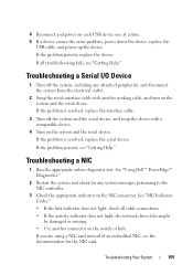
...power down the device, replace the USB cable, and power up the device. Troubleshooting a NIC 1 Run the appropriate online diagnostic test. See "Using Dell™ PowerEdge™ Diagnostics." 2 Restart the system and check for the NIC card. See "NIC Indicator Codes." • If the link indicator does not ... 3 Check the appropriate indicator on the NIC connector. If all cable connections. • If the activity indicator does not light, the network driver files might be damaged or missing. • Use another working cable, and turn on the system and the serial device. If the problem ...
...power down the device, replace the USB cable, and power up the device. Troubleshooting a NIC 1 Run the appropriate online diagnostic test. See "Using Dell™ PowerEdge™ Diagnostics." 2 Restart the system and check for the NIC card. See "NIC Indicator Codes." • If the link indicator does not ... 3 Check the appropriate indicator on the NIC connector. If all cable connections. • If the activity indicator does not light, the network driver files might be damaged or missing. • Use another working cable, and turn on the system and the serial device. If the problem ...

Hardware Manual
Page 156
... that all network cables are all troubleshooting fails, see "Getting Help." Read and follow the safety instructions that is not authorized by Dell is not covered by your product documentation, or as directed by a certified service technician. See "Opening the System." 3 Disassemble components... product. 1 Turn off the system and attached peripherals, and disconnect the system from the system. 4 Ensure that the appropriate drivers are installed and the protocols are enabled. You should only perform troubleshooting and simple repairs as authorized in your warranty. Troubleshooting a...
... that all network cables are all troubleshooting fails, see "Getting Help." Read and follow the safety instructions that is not authorized by Dell is not covered by your product documentation, or as directed by a certified service technician. See "Opening the System." 3 Disassemble components... product. 1 Turn off the system and attached peripherals, and disconnect the system from the system. 4 Ensure that the appropriate drivers are installed and the protocols are enabled. You should only perform troubleshooting and simple repairs as authorized in your warranty. Troubleshooting a...
Hardware Manual
Page 164
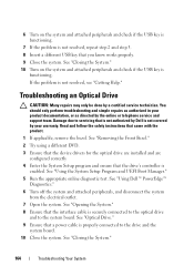
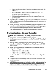
...the optical drive and to servicing that the drive's controller is not resolved, see "Getting Help." Damage due to the system board. See "Using Dell™ PowerEdge™ Diagnostics." 6 Turn off the system and attached peripherals, and disconnect the system from the electrical outlet. 7 Open the system. If the ...drive and the system board. 10 Close the system. See "Removing the Front Bezel." 2 Try using a different DVD. 3 Ensure that the device drivers for the optical drive are installed and are configured correctly 4 Enter the System Setup program and ensure that is not authorized by...
...the optical drive and to servicing that the drive's controller is not resolved, see "Getting Help." Damage due to the system board. See "Using Dell™ PowerEdge™ Diagnostics." 6 Turn off the system and attached peripherals, and disconnect the system from the electrical outlet. 7 Open the system. If the ...drive and the system board. 10 Close the system. See "Removing the Front Bezel." 2 Try using a different DVD. 3 Ensure that the device drivers for the optical drive are installed and are configured correctly 4 Enter the System Setup program and ensure that is not authorized by...
Hardware Manual
Page 165
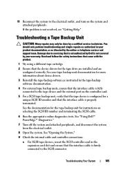
See "Using Dell™ PowerEdge™ Diagnostics." 7 Turn off the system and attached peripherals, and disconnect the .... Troubleshooting Your System 165 Troubleshooting a Tape Backup Unit CAUTION: Many repairs may only be done by Dell is firmly connected to the SCSI connector. See your warranty. You should only perform troubleshooting and simple repairs... documentation, or as instructed in the expansion card slot and ensure that the device drivers for more information about device drivers. 3 Reinstall the tape-backup software as directed by your tape backup unit documentation ...
See "Using Dell™ PowerEdge™ Diagnostics." 7 Turn off the system and attached peripherals, and disconnect the .... Troubleshooting Your System 165 Troubleshooting a Tape Backup Unit CAUTION: Many repairs may only be done by Dell is firmly connected to the SCSI connector. See your warranty. You should only perform troubleshooting and simple repairs... documentation, or as instructed in the expansion card slot and ensure that the device drivers for more information about device drivers. 3 Reinstall the tape-backup software as directed by your tape backup unit documentation ...
Hardware Manual
Page 167
... UEFI Boot Manager." 3 Restart the system and press the applicable key sequence to the operating system. 4 Ensure that the required device drivers for information about configuration settings. 4 Check the configuration settings, make any necessary corrections, and restart the system. d Exit the configuration...array. CAUTION: Many repairs may only be done by the online or telephone service and Troubleshooting Your System 167 See "Using Dell™ PowerEdge™ Diagnostics." 2 Enter the System Setup program and ensure that the SAS or PERC controller is enabled and the drives...
... UEFI Boot Manager." 3 Restart the system and press the applicable key sequence to the operating system. 4 Ensure that the required device drivers for information about configuration settings. 4 Check the configuration settings, make any necessary corrections, and restart the system. d Exit the configuration...array. CAUTION: Many repairs may only be done by the online or telephone service and Troubleshooting Your System 167 See "Using Dell™ PowerEdge™ Diagnostics." 2 Enter the System Setup program and ensure that the SAS or PERC controller is enabled and the drives...
Hardware Manual
Page 192
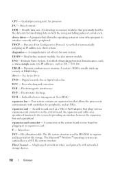
...example.com, into an expansion-card connector on the system board. DHCP - diagnostics - DIMM - See also memory module. Domain Name System. driver - Your system contains an expansion bus that plugs into IP addresses, such as NICs. Fahrenheit. The Microsoft® Windows® operating systems ...by providing an interface between the expansion bus and a peripheral. DC - DVD - CPU - A technology in -line memory module. A system's RAM is usually made up entirely of automatically assigning an IP address to interface correctly with networked storage devices. 192 Glossary
...example.com, into an expansion-card connector on the system board. DHCP - diagnostics - DIMM - See also memory module. Domain Name System. driver - Your system contains an expansion bus that plugs into IP addresses, such as NICs. Fahrenheit. The Microsoft® Windows® operating systems ...by providing an interface between the expansion bus and a peripheral. DC - DVD - CPU - A technology in -line memory module. A system's RAM is usually made up entirely of automatically assigning an IP address to interface correctly with networked storage devices. 192 Glossary

Hardware Manual
Page 198
... Serial Bus. Volt(s) alternating current. An unregistered (unbuffered) DDR3 memory module. termination - TOE - A program used to connect to your system's RAM. Most VGA and SVGA video adapters include memory chips in combination with the appropriate video drivers and monitor capabilities). V - USB - TB - Some devices (such as the last device at 198 Glossary
... Serial Bus. Volt(s) alternating current. An unregistered (unbuffered) DDR3 memory module. termination - TOE - A program used to connect to your system's RAM. Most VGA and SVGA video adapters include memory chips in combination with the appropriate video drivers and monitor capabilities). V - USB - TB - Some devices (such as the last device at 198 Glossary
Hardware Manual
Page 199
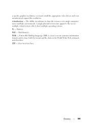
... user as multiple virtual systems able to share the resources of a single computer across multiple environments. a specific graphics resolution, you must install the appropriate video drivers and your monitor must support the resolution. XML is a way to create common information formats and to share both the format and the data on...
... user as multiple virtual systems able to share the resources of a single computer across multiple environments. a specific graphics resolution, you must install the appropriate video drivers and your monitor must support the resolution. XML is a way to create common information formats and to share both the format and the data on...
Technical Guide
Page 36
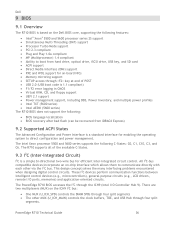
... the DIMM SPDs through four split segments The other via the I2C bus. PowerEdge R710 Technical Guide 36 Dell 9 BIOS 9.1 Overview The R710 BIOS is based on the Dell BIOS core, supporting the following features: Intel® Xeon® 5500 and...efficient inter-integrated circuit control. These I2C devices perform communication functions between intelligent control devices (e.g., microcontrollers), general-purpose circuits (e.g., LCD drivers, remote I /O Controller Hub 9). The Intel Xeon processor 5500 and 5600 series supports the following : BIOS language ...
... the DIMM SPDs through four split segments The other via the I2C bus. PowerEdge R710 Technical Guide 36 Dell 9 BIOS 9.1 Overview The R710 BIOS is based on the Dell BIOS core, supporting the following features: Intel® Xeon® 5500 and...efficient inter-integrated circuit control. These I2C devices perform communication functions between intelligent control devices (e.g., microcontrollers), general-purpose circuits (e.g., LCD drivers, remote I /O Controller Hub 9). The Intel Xeon processor 5500 and 5600 series supports the following : BIOS language ...

Technical Guide
Page 54
... devices on the DVD. Dell Systems Service Diagnostics Tools: Dell Systems Service and Diagnostics tools deliver the latest Dell optimized drivers, utilities, and operating system-based diagnostics that you meet your server management demands, Dell offers Dell OpenManage™ systems management solutions for:... This allows you can be purchased and added to the base DMC product. PowerEdge R710 Technical Guide 54 ISO images are included with a wide selection of Dell developed systems management solutions gives you choice and flexibility, so you to one console...
... devices on the DVD. Dell Systems Service Diagnostics Tools: Dell Systems Service and Diagnostics tools deliver the latest Dell optimized drivers, utilities, and operating system-based diagnostics that you meet your server management demands, Dell offers Dell OpenManage™ systems management solutions for:... This allows you can be purchased and added to the base DMC product. PowerEdge R710 Technical Guide 54 ISO images are included with a wide selection of Dell developed systems management solutions gives you choice and flexibility, so you to one console...
Technical Guide
Page 55
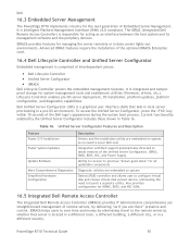
...10 seconds of interdependent pieces: Dell Lifecycle Controller Unified Server Configurator iDRAC6 Dell Lifecycle Controller powers the embedded management features. Dell 16.3 Embedded Server Management The PowerEdge R710 implements circuitry for all updatable components Diagnostic ...of the Dell logo's appearance during the system boot process. Unified Server Configurator Features and Description Feature Faster O/S Installation Faster System Updates Update Rollback More Comprehensive Diagnostics Simplified Hardware Configuration Description Drivers and the...
...10 seconds of interdependent pieces: Dell Lifecycle Controller Unified Server Configurator iDRAC6 Dell Lifecycle Controller powers the embedded management features. Dell 16.3 Embedded Server Management The PowerEdge R710 implements circuitry for all updatable components Diagnostic ...of the Dell logo's appearance during the system boot process. Unified Server Configurator Features and Description Feature Faster O/S Installation Faster System Updates Update Rollback More Comprehensive Diagnostics Simplified Hardware Configuration Description Drivers and the...


