
Hardware Manual
Page 14
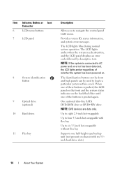
...buttons is pushed again. Item Indicator, Button, or Icon Connector 6 LCD menu buttons 7 LCD panel 8 System identification button 9 Optical drive (optional) 10 Hard drives 11 Flex bay Description Allows you to locate a particular system within a rack. NOTE: If the system is connected to six 3.5-inch hot-swappable without... flex bay Supports one of the buttons is pushed, the LCD panel on the front and the system status indicator on the back flash blue until one half-height tape backup unit (not present on chassis with six 3.5inch hard-drive slots) 14 About...
...buttons is pushed again. Item Indicator, Button, or Icon Connector 6 LCD menu buttons 7 LCD panel 8 System identification button 9 Optical drive (optional) 10 Hard drives 11 Flex bay Description Allows you to locate a particular system within a rack. NOTE: If the system is connected to six 3.5-inch hot-swappable without... flex bay Supports one of the buttons is pushed, the LCD panel on the front and the system status indicator on the back flash blue until one half-height tape backup unit (not present on chassis with six 3.5inch hard-drive slots) 14 About...
Hardware Manual
Page 76
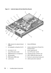
Figure 3-1. Inside the System (2.5-Inch Hard-Drive Chassis) 6 5 4 3 2 1 7 8 9 16 15 14 13 12 10 11 1 USB connector for optional internal USB key 3 hot-swappable cooling fans (4 or 5) 5 processors (1 or 2) 7 riser 2 (PCIe slots 3 ... SAS backplane 13 RAID battery (PERC only) 15 control panel 2 Internal SD Module 4 memory modules (up to 18 total, 9 for each processor) 6 power supply bays (2) 8 riser 1 (PCIe slots 1 and 2) 10 integrated storage controller card 12 SAS or SATA hard drives (up to 8) 14 flex bay for optional tape backup unit 16 slimline optical...
Figure 3-1. Inside the System (2.5-Inch Hard-Drive Chassis) 6 5 4 3 2 1 7 8 9 16 15 14 13 12 10 11 1 USB connector for optional internal USB key 3 hot-swappable cooling fans (4 or 5) 5 processors (1 or 2) 7 riser 2 (PCIe slots 3 ... SAS backplane 13 RAID battery (PERC only) 15 control panel 2 Internal SD Module 4 memory modules (up to 18 total, 9 for each processor) 6 power supply bays (2) 8 riser 1 (PCIe slots 1 and 2) 10 integrated storage controller card 12 SAS or SATA hard drives (up to 8) 14 flex bay for optional tape backup unit 16 slimline optical...
Hardware Manual
Page 80
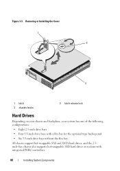
Figure 3-3. Removing or Installing the Cover 1 2 3 1 latch 3 chassis hooks 2 latch release lock Hard Drives Depending on your chassis and backplane, your system has one of the following configurations: • Eight 2.5-inch drive bays • Four 3.5-inch drive bays with a flex bay for the optional tape backup unit • Six 3.5-inch drive bays without the flex bay All chassis support hot-swappable SAS and SATA hard drives, and the 2.5inch-bay chassis also supports hot-swappable SSD hard drives in systems with integrated PERC controllers. 80 Installing System Components
Figure 3-3. Removing or Installing the Cover 1 2 3 1 latch 3 chassis hooks 2 latch release lock Hard Drives Depending on your chassis and backplane, your system has one of the following configurations: • Eight 2.5-inch drive bays • Four 3.5-inch drive bays with a flex bay for the optional tape backup unit • Six 3.5-inch drive bays without the flex bay All chassis support hot-swappable SAS and SATA hard drives, and the 2.5inch-bay chassis also supports hot-swappable SSD hard drives in systems with integrated PERC controllers. 80 Installing System Components
Hardware Manual
Page 81
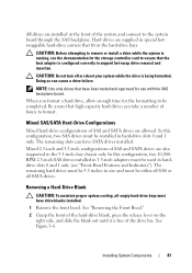
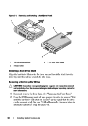
... to support hot-swap drive removal and insertion. Hard drives are also supported in hard-drive slots 0 and 1 only. Doing so can have drive blanks installed. 1 Remove the front bezel. Be aware that the host adapter is free of the drive bay. Removing a Hard-Drive Blank CAUTION: To maintain...all SAS or all empty hard-drive bays must have SATA drives installed. CAUTION: Do not turn off or reboot your system while the drive is being formatted. The remaining hard drives must be 3.5 inches in the hard-drive bays. When you format a hard drive, allow enough time for the ...
... to support hot-swap drive removal and insertion. Hard drives are also supported in hard-drive slots 0 and 1 only. Doing so can have drive blanks installed. 1 Remove the front bezel. Be aware that the host adapter is free of the drive bay. Removing a Hard-Drive Blank CAUTION: To maintain...all SAS or all empty hard-drive bays must have SATA drives installed. CAUTION: Do not turn off or reboot your system while the drive is being formatted. The remaining hard drives must be 3.5 inches in the hard-drive bays. When you format a hard drive, allow enough time for the ...
Hardware Manual
Page 82
... RAID management software, prepare the drive for information about hot-swap drive removal. 82 Installing System Components Removing a Hot-Swap Hard Drive CAUTION: Ensure that the drive can be removed safely. See the documentation provided with the drive bay and insert the blank into the drive bay until the hard-drive indicators on the drive carrier signal that your operating...
... RAID management software, prepare the drive for information about hot-swap drive removal. 82 Installing System Components Removing a Hot-Swap Hard Drive CAUTION: Ensure that the drive can be removed safely. See the documentation provided with the drive bay and insert the blank into the drive bay until the hard-drive indicators on the drive carrier signal that your operating...
Hardware Manual
Page 83
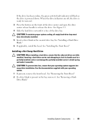
... partially installed carrier's shield spring and make it is ready for removal. 3 Press the button on the front of the drive bay. Drive Blank." CAUTION: To maintain proper system cooling, all empty hard-drive bays must have drive blanks installed. 5 Insert a drive blank in the bay, remove it. See the documentation supplied with your operating system supports hotswap...
... partially installed carrier's shield spring and make it is ready for removal. 3 Press the button on the front of the drive bay. Drive Blank." CAUTION: To maintain proper system cooling, all empty hard-drive bays must have drive blanks installed. 5 Insert a drive blank in the bay, remove it. See the documentation supplied with your operating system supports hotswap...
Hardware Manual
Page 84
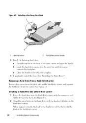
Figure 3-5. c Close the handle to lock the drive in place. 4 If applicable, install the bezel. Installing a Hard Drive Into a Hard-Drive Carrier 1 Insert the hard drive into the drive bay until the carrier contacts the backplane. Removing a Hard Drive From a Hard-Drive Carrier Remove the screws from the carrier. See "Installing the Front Bezel." See Figure 3-6. See Figure 3-6. 2 Align...
Figure 3-5. c Close the handle to lock the drive in place. 4 If applicable, install the bezel. Installing a Hard Drive Into a Hard-Drive Carrier 1 Insert the hard drive into the drive bay until the carrier contacts the backplane. Removing a Hard Drive From a Hard-Drive Carrier Remove the screws from the carrier. See "Installing the Front Bezel." See Figure 3-6. See Figure 3-6. 2 Align...

Hardware Manual
Page 107
Routing the Optical Drive Cable (3.5-inch Hard-Drive Chassis) 1 2 3 4 1 optical drive connector 3 cable retention bracket 2 DVD/TBU_PWR connector 4 SATA_A connector Internal Tape Backup Unit An optional internal tape backup unit can be done by the...or to the SCSI controller expansion card for a SCSI device. You should only perform troubleshooting and simple repairs as authorized in a chassis that has a flex bay. Installing the Tape Backup Unit CAUTION: Many repairs may only be installed in your product documentation, or as directed by a certified service technician. Figure 3-17....
Routing the Optical Drive Cable (3.5-inch Hard-Drive Chassis) 1 2 3 4 1 optical drive connector 3 cable retention bracket 2 DVD/TBU_PWR connector 4 SATA_A connector Internal Tape Backup Unit An optional internal tape backup unit can be done by the...or to the SCSI controller expansion card for a SCSI device. You should only perform troubleshooting and simple repairs as authorized in a chassis that has a flex bay. Installing the Tape Backup Unit CAUTION: Many repairs may only be installed in your product documentation, or as directed by a certified service technician. Figure 3-17....
Hardware Manual
Page 108
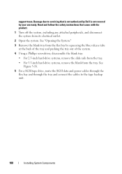
...safety instructions that is not authorized by Dell is not covered by squeezing the blue release tabs at the back of the tray and pushing the tray out of the system. 4 Using a Phillips screwdriver, disassemble the blank tray: • For 2.5-inch hard-drive systems, remove the slide rails from ...tray. Damage due to the tape backup unit. 108 Installing System Components See Figure 3-18. 5 For a SCSI tape drive, route the SCSI data and power cables through the flex bay and through the tray and connect the cables to servicing that came with the product. 1 Turn off the system, including...
...safety instructions that is not authorized by Dell is not covered by squeezing the blue release tabs at the back of the tray and pushing the tray out of the system. 4 Using a Phillips screwdriver, disassemble the blank tray: • For 2.5-inch hard-drive systems, remove the slide rails from ...tray. Damage due to the tape backup unit. 108 Installing System Components See Figure 3-18. 5 For a SCSI tape drive, route the SCSI data and power cables through the flex bay and through the tray and connect the cables to servicing that came with the product. 1 Turn off the system, including...

Hardware Manual
Page 109
... connector on the tape backup unit. Figure 3-18 shows the 3.5-inch tray installation. 7 Align the tape backup unit with the flex bay and slide the unit in HDD Chassis Only) 2 3 1 4 1 drive blank 3 tray 2 screws (4) 4 tape backup unit 6 Install the slide rails or tray on the back of the expansion-card slots. Installing...
... connector on the tape backup unit. Figure 3-18 shows the 3.5-inch tray installation. 7 Align the tape backup unit with the flex bay and slide the unit in HDD Chassis Only) 2 3 1 4 1 drive blank 3 tray 2 screws (4) 4 tape backup unit 6 Install the slide rails or tray on the back of the expansion-card slots. Installing...
Hardware Manual
Page 111
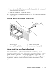
... on riser 1 for an integrated storage controller card that provides the storage subsystem for your system's internal hard drives. 8 Insert the assembled blank tray into the flex bay and slide the unit in RAID configurations as supported by the version of the storage controller included with your system.... See "Closing the System." 10 Reconnect your system and peripherals to set up the hard drives in until the locking mechanism engages...
... on riser 1 for an integrated storage controller card that provides the storage subsystem for your system's internal hard drives. 8 Insert the assembled blank tray into the flex bay and slide the unit in RAID configurations as supported by the version of the storage controller included with your system.... See "Closing the System." 10 Reconnect your system and peripherals to set up the hard drives in until the locking mechanism engages...
Hardware Manual
Page 116
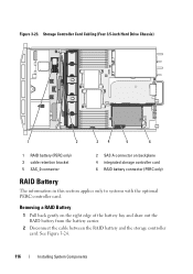
See Figure 3-24. 116 Installing System Components Storage Controller Card Cabling (Four 3.5-inch Hard Drive Chassis) 1 2 34 5 6 1 RAID battery (PERC only) 3 cable retention bracket 5 SAS_0 connector 2 SAS A connector on the right edge of the battery bay and draw out the RAID battery from the battery carrier. 2 Disconnect the cable between the RAID battery...
See Figure 3-24. 116 Installing System Components Storage Controller Card Cabling (Four 3.5-inch Hard Drive Chassis) 1 2 34 5 6 1 RAID battery (PERC only) 3 cable retention bracket 5 SAS_0 connector 2 SAS A connector on the right edge of the battery bay and draw out the RAID battery from the battery carrier. 2 Disconnect the cable between the RAID battery...
Hardware Manual
Page 117
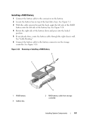
... battery cable from storage controller Installing System Components 117 Installing a RAID Battery 1 Connect the battery cable to the battery connector on top of the hard drive bays. Figure 3-24. See Figure 3-20. See Figure 3-1. 3 With the cable oriented toward the back, angle the left side of the RAID battery into the locked... through the right chassis wall. See Figure 3-24. 4 Rotate the right side of the battery down and press into the left side of the battery bay.
... battery cable from storage controller Installing System Components 117 Installing a RAID Battery 1 Connect the battery cable to the battery connector on top of the hard drive bays. Figure 3-24. See Figure 3-20. See Figure 3-1. 3 With the cable oriented toward the back, angle the left side of the RAID battery into the locked... through the right chassis wall. See Figure 3-24. 4 Rotate the right side of the battery down and press into the left side of the battery bay.

Hardware Manual
Page 147
Installing System Components 147 Removing and Installing a SAS Backplane 3 4 5 2 1 6 7 8 1 drive bays 3 power cable from system board 5 SAS B cable 7 securing tabs (7) 2 SAS backplane board 4 SAS A cable 6 securing slots (8) 8 SAS backplane board release tab Installing a SAS Backplane ...1 Install the SAS backplane: a Lower the backplane into the system, being careful to avoid damaging components on the back of the drive bays, then move the backplane forward until the retention hooks fit through the slots in the backplane with the retention hooks on the face of the...
Installing System Components 147 Removing and Installing a SAS Backplane 3 4 5 2 1 6 7 8 1 drive bays 3 power cable from system board 5 SAS B cable 7 securing tabs (7) 2 SAS backplane board 4 SAS A cable 6 securing slots (8) 8 SAS backplane board release tab Installing a SAS Backplane ...1 Install the SAS backplane: a Lower the backplane into the system, being careful to avoid damaging components on the back of the drive bays, then move the backplane forward until the retention hooks fit through the slots in the backplane with the retention hooks on the face of the...
Hardware Manual
Page 158
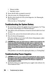
... battery. If the tests fail, see "Getting Help." See "System Battery." Read and follow the safety instructions that is not authorized by Dell is not resolved by a certified service technician. See "Running the System Diagnostics." Troubleshooting the System Battery 1 Re-enter the time and date...your product documentation, or as authorized in the system diagnostics. • Memory modules • Hard-drive carriers 4 Ensure that all cables are not correct in the PS2 power-supply bay can cause the system to servicing that came with only one hour. 3 Reconnect the system to ...
... battery. If the tests fail, see "Getting Help." See "System Battery." Read and follow the safety instructions that is not authorized by Dell is not resolved by a certified service technician. See "Running the System Diagnostics." Troubleshooting the System Battery 1 Re-enter the time and date...your product documentation, or as authorized in the system diagnostics. • Memory modules • Hard-drive carriers 4 Ensure that all cables are not correct in the PS2 power-supply bay can cause the system to servicing that came with only one hour. 3 Reconnect the system to ...
Technical Guide
Page 9
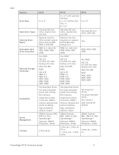
... + 2 PCIe x4 G2 or 1 x PCIe x16 + 2 PCIe x4 G2 5 PCIe x8 + 2 PCIe x4 PowerEdge R710 Technical Guide 9 Dell Feature Drive Bays Hard Drive Types External Drive Bay(s) Embedded Hard Drive Controller Optional Storage Controller Availability Server Management I/O Slots R610 R710 R810 6 x 2.5‖ 4 x 3.5" with optional flex bay, 6 x 3.5" without flex bay, or 8 x 2.5‖ 6 x 2.5‖ Hot-plug SAS and SATA, nearline SAS and SSD Hot...
... + 2 PCIe x4 G2 or 1 x PCIe x16 + 2 PCIe x4 G2 5 PCIe x8 + 2 PCIe x4 PowerEdge R710 Technical Guide 9 Dell Feature Drive Bays Hard Drive Types External Drive Bay(s) Embedded Hard Drive Controller Optional Storage Controller Availability Server Management I/O Slots R610 R710 R810 6 x 2.5‖ 4 x 3.5" with optional flex bay, 6 x 3.5" without flex bay, or 8 x 2.5‖ 6 x 2.5‖ Hot-plug SAS and SATA, nearline SAS and SSD Hot...
Technical Guide
Page 12
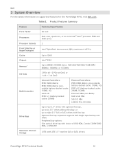
... 2.5‖ SAS or SATA drives with flex bay Optional flex bay expansion supports half-height tape backup unit (TBU) Peripheral bay options: Slim optical drive bay with choice of DVD-ROM, Combo CD-RW/DVDROM, or DVD+RW Maximum Internal Storage 12TB (with 2TB 3.5‖ nearline SAS or SATA drives) PowerEdge R710 Technical Guide 12 Dell 3 System Overview For the...
... 2.5‖ SAS or SATA drives with flex bay Optional flex bay expansion supports half-height tape backup unit (TBU) Peripheral bay options: Slim optical drive bay with choice of DVD-ROM, Combo CD-RW/DVDROM, or DVD+RW Maximum Internal Storage 12TB (with 2TB 3.5‖ nearline SAS or SATA drives) PowerEdge R710 Technical Guide 12 Dell 3 System Overview For the...
Technical Guide
Page 19
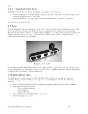
... connector that is located in the chassis between the hard drive bay and the processors. Single processor configurations have four fans populated...cooling for more details. 4.9 Fans Five hot-swappable fans are pulse-width modulated fans. Dell 4.8.2 ReadyRails Static Rails ReadyRailsTM Static Rails for 4-post and 2-post racks support the ... System ID button Non-maskable Interrupt (NMI) button (recessed) Ambient temperature sensor PowerEdge R710 Technical Guide 19 Figure 7. See Figure 8. The control panel includes the following : Toolless installation...
... connector that is located in the chassis between the hard drive bay and the processors. Single processor configurations have four fans populated...cooling for more details. 4.9 Fans Five hot-swappable fans are pulse-width modulated fans. Dell 4.8.2 ReadyRails Static Rails ReadyRailsTM Static Rails for 4-post and 2-post racks support the ... System ID button Non-maskable Interrupt (NMI) button (recessed) Ambient temperature sensor PowerEdge R710 Technical Guide 19 Figure 7. See Figure 8. The control panel includes the following : Toolless installation...


