

Glossary
Page 8
...Data stored in the event of an electrical failure. When such devices are video standards for operation. uplink port - A battery-powered unit that automatically supplies power to your system in memory that allows a network manager to configure your system's integral ... such as password protection. A USB connector provides a single connection point for the devices. See also guarding, mirroring, and RAID. system memory - Transmission Control Protocol/Internet Protocol. Used to other hubs or switches without requiring a crossover cable. SNMP - striping - A virtual disk...
...Data stored in the event of an electrical failure. When such devices are video standards for operation. uplink port - A battery-powered unit that automatically supplies power to your system in memory that allows a network manager to configure your system's integral ... such as password protection. A USB connector provides a single connection point for the devices. See also guarding, mirroring, and RAID. system memory - Transmission Control Protocol/Internet Protocol. Used to other hubs or switches without requiring a crossover cable. SNMP - striping - A virtual disk...
Hardware Owner's Manual
Page 7
Removing an Integrated Storage Controller Card 112 Installing an Integrated Storage Controller Card 114 Removing the Expansion Card Stabilizer Bracket 115 Installing the Expansion Card Stabilizer Bracket 116 RAID Battery 117 Removing a RAID Battery 117 Installing a RAID Battery 118 Expansion Cards 118 Expansion Card ... 130 Processors 131 Removing a Processor 131 Installing a Processor 134 System Battery 136 Replacing the System Battery 136 Control Panel Assembly 138 Removing the Control Panel Assembly 138 Installing the Control Panel Assembly 141 SAS Backplane 142 Contents 7
Removing an Integrated Storage Controller Card 112 Installing an Integrated Storage Controller Card 114 Removing the Expansion Card Stabilizer Bracket 115 Installing the Expansion Card Stabilizer Bracket 116 RAID Battery 117 Removing a RAID Battery 117 Installing a RAID Battery 118 Expansion Cards 118 Expansion Card ... 130 Processors 131 Removing a Processor 131 Installing a Processor 134 System Battery 136 Replacing the System Battery 136 Control Panel Assembly 138 Removing the Control Panel Assembly 138 Installing the Control Panel Assembly 141 SAS Backplane 142 Contents 7
Hardware Owner's Manual
Page 26
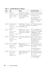
E1210 Motherboard CMOS battery is missing See "Troubleshooting the battery or the voltage is either Reseat the RAID battery Controller missing, bad, or unable to connector. battery. Check issues. E1229 CPU # VCORE Regulator failure. Table 1-1. See "Troubleshooting System Cooling Problems." failure. Check the allowable range. See "Installing battery recharge due to the disabled, temp allowable temperature and system...
E1210 Motherboard CMOS battery is missing See "Troubleshooting the battery or the voltage is either Reseat the RAID battery Controller missing, bad, or unable to connector. battery. Check issues. E1229 CPU # VCORE Regulator failure. Table 1-1. See "Troubleshooting System Cooling Problems." failure. Check the allowable range. See "Installing battery recharge due to the disabled, temp allowable temperature and system...
Hardware Owner's Manual
Page 37
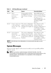
...NOTE: If you of an abbreviation or acronym used in the table, check the documentation for an explanation of sustained charge. Allow RAID battery to charge to notify you receive a system message not listed in this table, see the "Glossary." W1628 Performance The system configuration ...provide, but it can hardware configuration or config. LCD Status Messages (continued) Code Text Causes Corrective Actions W1228 RAID Controller battery capacity < 24hr. provide. requires more power than 24 hours of charge left. power supplies, and then restart the system.
...NOTE: If you of an abbreviation or acronym used in the table, check the documentation for an explanation of sustained charge. Allow RAID battery to charge to notify you receive a system message not listed in this table, see the "Glossary." W1628 Performance The system configuration ...provide, but it can hardware configuration or config. LCD Status Messages (continued) Code Text Causes Corrective Actions W1228 RAID Controller battery capacity < 24hr. provide. requires more power than 24 hours of charge left. power supplies, and then restart the system.
Hardware Owner's Manual
Page 79
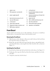
... the chassis. 1 system cover 3 PCIe expansion card slots (5) 5 power supply bays (2) 7 heat sink and processor (1 or 2) 9 internal USB module 11 control panel 13 optical drive (optional) 15 integrated storage controller card 17 RAID battery (optional) 2 cooling shroud 4 heat sink blank (single-processor configuration) 6 memory modules (up to 12 total, 6 for each processor) 8 system feet...
... the chassis. 1 system cover 3 PCIe expansion card slots (5) 5 power supply bays (2) 7 heat sink and processor (1 or 2) 9 internal USB module 11 control panel 13 optical drive (optional) 15 integrated storage controller card 17 RAID battery (optional) 2 cooling shroud 4 heat sink blank (single-processor configuration) 6 memory modules (up to 12 total, 6 for each processor) 8 system feet...
Hardware Owner's Manual
Page 113
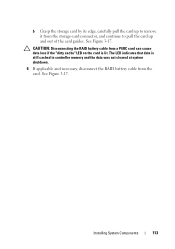
See Figure 3-17. See Figure 3-17. Installing System Components 113 CAUTION: Disconnecting the RAID battery cable from a PERC card can cause data loss if the "dirty cache" LED on the card is still cached in controller memory and the data was not cleared at system shutdown. 6 If applicable and necessary, disconnect the RAID battery cable from the storage-card connector, and continue to pull the card up to remove it from the card. b Grasp the storage card by its edge, carefully pull the card up and out of the card guides. The LED indicates that data is lit.
See Figure 3-17. See Figure 3-17. Installing System Components 113 CAUTION: Disconnecting the RAID battery cable from a PERC card can cause data loss if the "dirty cache" LED on the card is still cached in controller memory and the data was not cleared at system shutdown. 6 If applicable and necessary, disconnect the RAID battery cable from the storage-card connector, and continue to pull the card up to remove it from the card. b Grasp the storage card by its edge, carefully pull the card up and out of the card guides. The LED indicates that data is lit.
Hardware Owner's Manual
Page 114
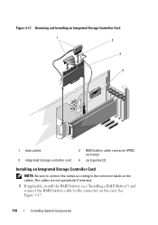
Removing and Installing an Integrated Storage Controller Card 1 2 3 4 1 data cables 3 integrated storage controller card 2 RAID battery cable connector (PERC card only) 4 card guides (2) Installing an Integrated Storage Controller Card NOTE: Be sure to connect the cables according to the connector on the cables. The cables are not operational if reversed. 1 If applicable, install the RAID battery (see "Installing a RAID Battery") and connect the RAID battery cable to the connector labels on the card. See Figure 3-17. 114 Installing System Components Figure 3-17.
Removing and Installing an Integrated Storage Controller Card 1 2 3 4 1 data cables 3 integrated storage controller card 2 RAID battery cable connector (PERC card only) 4 card guides (2) Installing an Integrated Storage Controller Card NOTE: Be sure to connect the cables according to the connector on the cables. The cables are not operational if reversed. 1 If applicable, install the RAID battery (see "Installing a RAID Battery") and connect the RAID battery cable to the connector labels on the card. See Figure 3-17. 114 Installing System Components Figure 3-17.
Hardware Owner's Manual
Page 116
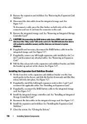
...slots 2 and 3 and reconnect the applicable cables. See "Installing an Integrated Storage Controller Card." 5 Reconnect the data cables to the integrated storage card. See Figure 3-17. CAUTION: Disconnecting the RAID battery cable from the integrated storage card. See "Installing an Expansion Card." 3 If ... tab on the expansion card stabilizer bracket over the four metal guides in controller memory and the data was not cleared at system shutdown. 6 If applicable and necessary, disconnect the RAID battery cable from the connector on both sides of the chassis. Installing the Expansion...
...slots 2 and 3 and reconnect the applicable cables. See "Installing an Integrated Storage Controller Card." 5 Reconnect the data cables to the integrated storage card. See Figure 3-17. CAUTION: Disconnecting the RAID battery cable from the integrated storage card. See "Installing an Expansion Card." 3 If ... tab on the expansion card stabilizer bracket over the four metal guides in controller memory and the data was not cleared at system shutdown. 6 If applicable and necessary, disconnect the RAID battery cable from the connector on both sides of the chassis. Installing the Expansion...
Hardware Owner's Manual
Page 117
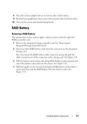
... connector on the integrated storage card. RAID Battery Removing a RAID Battery The information in the battery carrier and draw out the RAID battery from the connector on the storage card. Installing System Components 117 See "Removing an Integrated Storage Controller Card." 2 Disconnect the RAID battery cable from the battery carrier. Press the tab on the RAID battery cable connector, and gently pull the...
... connector on the integrated storage card. RAID Battery Removing a RAID Battery The information in the battery carrier and draw out the RAID battery from the connector on the storage card. Installing System Components 117 See "Removing an Integrated Storage Controller Card." 2 Disconnect the RAID battery cable from the battery carrier. Press the tab on the RAID battery cable connector, and gently pull the...
Hardware Owner's Manual
Page 118
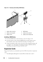
...the integrated storage card (see Figure 3-17) and replace the integrated storage controller card. See Figure 3-18. 3 Connect the battery cable to five PCIe Generation 2 expansion cards: • Two full-height...battery carrier with the RAID battery into the battery carrier slots until the carrier release latch locks into the battery carrier. Removing and Installing a RAID Battery 1 2 3 6 5 4 1 battery cable connector 3 battery carrier tabs (2) 5 battery carrier 2 RAID battery 4 battery carrier slots (2) 6 battery carrier release tab Installing a RAID Battery 1 Insert the RAID battery...
...the integrated storage card (see Figure 3-17) and replace the integrated storage controller card. See Figure 3-18. 3 Connect the battery cable to five PCIe Generation 2 expansion cards: • Two full-height...battery carrier with the RAID battery into the battery carrier slots until the carrier release latch locks into the battery carrier. Removing and Installing a RAID Battery 1 2 3 6 5 4 1 battery cable connector 3 battery carrier tabs (2) 5 battery carrier 2 RAID battery 4 battery carrier slots (2) 6 battery carrier release tab Installing a RAID Battery 1 Insert the RAID battery...
Hardware Owner's Manual
Page 171
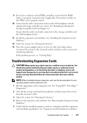
... See "Installing the Expansion Card Stabilizer." 12 Close the system. 9 If you have a battery-cached PERC controller, ensure that the RAID battery is properly connected and, if applicable, the memory module on the system and attached peripherals. See "Using Dell™ PowerEdge™ Diagnostics." 2 Turn off the system and attached peripherals, and disconnect the system from...
... See "Installing the Expansion Card Stabilizer." 12 Close the system. 9 If you have a battery-cached PERC controller, ensure that the RAID battery is properly connected and, if applicable, the memory module on the system and attached peripherals. See "Using Dell™ PowerEdge™ Diagnostics." 2 Turn off the system and attached peripherals, and disconnect the system from...
Hardware Owner's Manual
Page 199
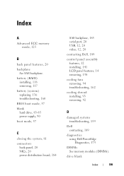
battery (RAID) installing, 118 removing, 117 battery (system) replacing, 136 troubleshooting, 160 BIOS boot mode, 57 blank hard drive, 83-85 power supply, 90 boot mode, 57 C closing the system, 81 connectors ..., 20 USB, 12, 20 video, 12, 20 contacting Dell, 189 control panel assembly features, 12 installing, 141 LCD panel features, 14 removing, 138 cooling fans removing, 94 troubleshooting, 162 cooling shroud installing, 93 removing, 92 D damaged systems troubleshooting, 159 Dell contacting, 189 diagnostics using Dell PowerEdge Diagnostics, 175 DIMMs See memory modules (DIMMs). drive blank...
battery (RAID) installing, 118 removing, 117 battery (system) replacing, 136 troubleshooting, 160 BIOS boot mode, 57 blank hard drive, 83-85 power supply, 90 boot mode, 57 C closing the system, 81 connectors ..., 20 USB, 12, 20 video, 12, 20 contacting Dell, 189 control panel assembly features, 12 installing, 141 LCD panel features, 14 removing, 138 cooling fans removing, 94 troubleshooting, 162 cooling shroud installing, 93 removing, 92 D damaged systems troubleshooting, 159 Dell contacting, 189 diagnostics using Dell PowerEdge Diagnostics, 175 DIMMs See memory modules (DIMMs). drive blank...
Hardware Owner's Manual
Page 200
... I iDRAC Configuration Utility, 75 iDRAC6 Enterprise card installing, 103 removing, 105 indicators back-panel, 20 front-panel, 12 NIC, 24 power, 12, 21 installing battery (RAID), 118 control panel assembly, 141 cooling shroud, 93 expansion card stabilizer, 91 expansion cards, 120 front bezel, 79 hard drive blank, 84 hard drive in a drive carrier...
... I iDRAC Configuration Utility, 75 iDRAC6 Enterprise card installing, 103 removing, 105 indicators back-panel, 20 front-panel, 12 NIC, 24 power, 12, 21 installing battery (RAID), 118 control panel assembly, 141 cooling shroud, 93 expansion card stabilizer, 91 expansion cards, 120 front bezel, 79 hard drive blank, 84 hard drive in a drive carrier...
Hardware Owner's Manual
Page 201
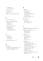
... memory modules, 128 optical drive, 109 power distribution board, 147 power supplies, 89 processor, 134 RAID battery, 118 SAS backplane, 144 system board, 151 tape drive, 109 USB memory key, 102 VFlash SD card, 106 Integrated Dell Remote Access Controller See iDRAC6 Enterprise card. LCD panel features, 14 menus, 16 M memory troubleshooting, 163 Memory...
... memory modules, 128 optical drive, 109 power distribution board, 147 power supplies, 89 processor, 134 RAID battery, 118 SAS backplane, 144 system board, 151 tape drive, 109 USB memory key, 102 VFlash SD card, 106 Integrated Dell Remote Access Controller See iDRAC6 Enterprise card. LCD panel features, 14 menus, 16 M memory troubleshooting, 163 Memory...
Hardware Owner's Manual
Page 203
...serial port connector, 20 setup password, 74 SSD hard drives, 82 startup accessing system features, 11 storage controller card installing, 114 removing, 112 troubleshooting, 170 support contacting Dell, 189 system closing, 81 opening, 80 system board connectors, 179 installing, 151 jumpers, 179 removing, ... 130 optical drive, 107 power distribution board, 146 power supplies, 88 processor, 131 RAID battery, 117 SAS backplane, 142 system board, 148 tape drive, 107 USB memory key, 102 replacing system battery, 136 S safety, 155 SAS backplane installing, 144 removing, 142 SAS controller See storage...
...serial port connector, 20 setup password, 74 SSD hard drives, 82 startup accessing system features, 11 storage controller card installing, 114 removing, 112 troubleshooting, 170 support contacting Dell, 189 system closing, 81 opening, 80 system board connectors, 179 installing, 151 jumpers, 179 removing, ... 130 optical drive, 107 power distribution board, 146 power supplies, 88 processor, 131 RAID battery, 117 SAS backplane, 142 system board, 148 tape drive, 107 USB memory key, 102 replacing system battery, 136 S safety, 155 SAS backplane installing, 144 removing, 142 SAS controller See storage...


