

Glossary
Page 6
...Object identifier is an extension of pixels up and down. parity - PERC - PXE - ns - Nanosecond(s). NVRAM - partition - You can contain multiple logical drives. You must usually be revised to a system. PDU - PowerEdge RAID controller. pixel - A video resolution, such as 640 x 480, is ... an image. NVRAM is a synonym for one processor must format each logical drive with a block of sources. Redundant information that controls the interpretation and execution of booting a system via a LAN (without a hard drive or bootable diskette). NMI - In RAID arrays...
...Object identifier is an extension of pixels up and down. parity - PERC - PXE - ns - Nanosecond(s). NVRAM - partition - You can contain multiple logical drives. You must usually be revised to a system. PDU - PowerEdge RAID controller. pixel - A video resolution, such as 640 x 480, is ... an image. NVRAM is a synonym for one processor must format each logical drive with a block of sources. Redundant information that controls the interpretation and execution of booting a system via a LAN (without a hard drive or bootable diskette). NMI - In RAID arrays...
Glossary
Page 46
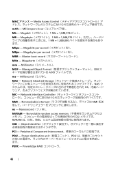
... NVRAM - Megahertz mm - Managed Object Format CIM ASCII ms - Nonvolatile random access memory NVRAM OID - Millimeter MOF - Network Interface Controller NMI - Object Identifier PCI - Megabytes per second MBps - Power distribution unit PDU PERC - Megabit 1 Mb = 1,048,576 MB - Megabits per second MBR - Master boot record MHz - Millisecond NAS - Nonmaskable interrupt NMI ns...
... NVRAM - Megahertz mm - Managed Object Format CIM ASCII ms - Nonvolatile random access memory NVRAM OID - Millimeter MOF - Network Interface Controller NMI - Object Identifier PCI - Megabytes per second MBps - Power distribution unit PDU PERC - Megabit 1 Mb = 1,048,576 MB - Megabits per second MBR - Master boot record MHz - Millisecond NAS - Nonmaskable interrupt NMI ns...
Glossary
Page 56
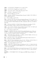
PowerEdge RAID POST Power-On Self-Test POST RAM PXE Preboot eXecution Environment LAN R-DIMM DDR3 Registered DDR3 Memory Module 56 MBps Megabytes per second Mbps ... Master Boot Record MHz Megahertz mm Millimeter MOF Managed Object Format) 은 CIM ASCII ms Millisecond NAS Network Attached Storage NAS NAS NIC Network Interface Controller NMI Nonmaskable Interrupt NMI ns Nanosecond NVRAM Nonvolatile Random-Access Memory NVRAM OID Object Identifier PCI Peripheral Component Interconnect PDU Power Distribution Unit...
PowerEdge RAID POST Power-On Self-Test POST RAM PXE Preboot eXecution Environment LAN R-DIMM DDR3 Registered DDR3 Memory Module 56 MBps Megabytes per second Mbps ... Master Boot Record MHz Megahertz mm Millimeter MOF Managed Object Format) 은 CIM ASCII ms Millisecond NAS Network Attached Storage NAS NAS NIC Network Interface Controller NMI Nonmaskable Interrupt NMI ns Nanosecond NVRAM Nonvolatile Random-Access Memory NVRAM OID Object Identifier PCI Peripheral Component Interconnect PDU Power Distribution Unit...
Dell PowerEdge Deployment Guide
Page 6
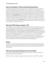
...mass storage driver for the controller in mind that there will need to support iSCSI and TOE. Please keep in your server, such as the PERC 6, is complete. Remember...be downloaded from a USB key by looking in the Microsoft Knowledge Base article 254078 on Dell Servers with ADS when two Intel™ Xeon™ processors are installing, the mass...problem. You will look for a floppy disk for a detailed explanation. For more information. PowerEdge Deployment Guide Manual Installation of the operating system installation. Operating systems released prior to Microsoft Windows...
...mass storage driver for the controller in mind that there will need to support iSCSI and TOE. Please keep in your server, such as the PERC 6, is complete. Remember...be downloaded from a USB key by looking in the Microsoft Knowledge Base article 254078 on Dell Servers with ADS when two Intel™ Xeon™ processors are installing, the mass...problem. You will look for a floppy disk for a detailed explanation. For more information. PowerEdge Deployment Guide Manual Installation of the operating system installation. Operating systems released prior to Microsoft Windows...
Deploying UEFI-Aware Operating Systems on Dell PowerEdge Servers
Page 10
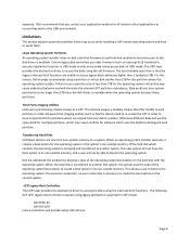
... create the boot option on a system. Be aware that the legacy interrupt 0x13 functions are stored in UEFI mode: Dell PERC 6/i Dell SAS 6/iR Future controllers will not have unique GUIDs for all mission‐critical applications to avoid them. Certain legacy disk... to ensure they work in its non‐volatile memory, and a user will eliminate the inherent GPT partition redundancy. The following Dell UEFI Legacy boot controllers operate using a partition or virtual disk smaller than 2TB for the operating system in the system's non‐volatile memory. This...
... create the boot option on a system. Be aware that the legacy interrupt 0x13 functions are stored in UEFI mode: Dell PERC 6/i Dell SAS 6/iR Future controllers will not have unique GUIDs for all mission‐critical applications to avoid them. Certain legacy disk... to ensure they work in its non‐volatile memory, and a user will eliminate the inherent GPT partition redundancy. The following Dell UEFI Legacy boot controllers operate using a partition or virtual disk smaller than 2TB for the operating system in the system's non‐volatile memory. This...

Hardware Owner's Manual
Page 11
See "Using the System Setup Program and UEFI Boot Manager." Enters the utility to configure NIC settings for your SAS controller. Enters the PERC configuration utility. Enters the SAS Configuration Utility. For more information, see the documentation for PXE boot. Starts PXE boot. For more.... Keystroke Description Enters the System Setup program. Enters the BIOS Boot Manager or the UEFI Boot Manager, depending on your PERC card. About Your System Accessing System Features During Startup The following keystrokes provide access to the system.
See "Using the System Setup Program and UEFI Boot Manager." Enters the utility to configure NIC settings for your SAS controller. Enters the PERC configuration utility. Enters the SAS Configuration Utility. For more information, see the documentation for PXE boot. Starts PXE boot. For more.... Keystroke Description Enters the System Setup program. Enters the BIOS Boot Manager or the UEFI Boot Manager, depending on your PERC card. About Your System Accessing System Features During Startup The following keystrokes provide access to the system.
Hardware Owner's Manual
Page 82
CAUTION: Before attempting to remove or install a drive while the system is running, see the documentation for the storage controller card to ensure that fit in the hard-drive bays. c Press the latch end of the cover, opposite from the cover release latch, into the ... chassis support hot-swappable SAS and SATA hard drives, and the 2.5inch-bay chassis also supports hot-swappable SSD hard drives in systems with integrated PERC controllers. b Lower the cover into place.
CAUTION: Before attempting to remove or install a drive while the system is running, see the documentation for the storage controller card to ensure that fit in the hard-drive bays. c Press the latch end of the cover, opposite from the cover release latch, into the ... chassis support hot-swappable SAS and SATA hard drives, and the 2.5inch-bay chassis also supports hot-swappable SSD hard drives in systems with integrated PERC controllers. b Lower the cover into place.
Hardware Owner's Manual
Page 113
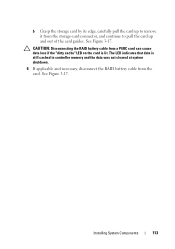
CAUTION: Disconnecting the RAID battery cable from the storage-card connector, and continue to pull the card up to remove it from a PERC card can cause data loss if the "dirty cache" LED on the card is still cached in controller memory and the data was not cleared at system shutdown. 6 If applicable and necessary, disconnect the RAID battery cable from the card. b Grasp the storage card by its edge, carefully pull the card up and out of the card guides. See Figure 3-17. Installing System Components 113 See Figure 3-17. The LED indicates that data is lit.
CAUTION: Disconnecting the RAID battery cable from the storage-card connector, and continue to pull the card up to remove it from a PERC card can cause data loss if the "dirty cache" LED on the card is still cached in controller memory and the data was not cleared at system shutdown. 6 If applicable and necessary, disconnect the RAID battery cable from the card. b Grasp the storage card by its edge, carefully pull the card up and out of the card guides. See Figure 3-17. Installing System Components 113 See Figure 3-17. The LED indicates that data is lit.
Hardware Owner's Manual
Page 114
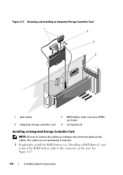
See Figure 3-17. 114 Installing System Components Figure 3-17. The cables are not operational if reversed. 1 If applicable, install the RAID battery (see "Installing a RAID Battery") and connect the RAID battery cable to the connector labels on the card. Removing and Installing an Integrated Storage Controller Card 1 2 3 4 1 data cables 3 integrated storage controller card 2 RAID battery cable connector (PERC card only) 4 card guides (2) Installing an Integrated Storage Controller Card NOTE: Be sure to connect the cables according to the connector on the cables.
See Figure 3-17. 114 Installing System Components Figure 3-17. The cables are not operational if reversed. 1 If applicable, install the RAID battery (see "Installing a RAID Battery") and connect the RAID battery cable to the connector labels on the card. Removing and Installing an Integrated Storage Controller Card 1 2 3 4 1 data cables 3 integrated storage controller card 2 RAID battery cable connector (PERC card only) 4 card guides (2) Installing an Integrated Storage Controller Card NOTE: Be sure to connect the cables according to the connector on the cables.
Hardware Owner's Manual
Page 116
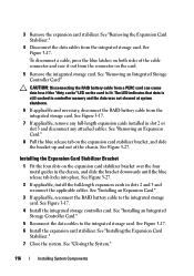
...: Disconnecting the RAID battery cable from a PERC card can cause data loss if the "dirty cache" LED on the card is still cached in the chassis, and slide the bracket downwards until the blue release tab locks into place. See Figure 3-17. 4 Install the integrated storage controller card. See Figure 3-17. The...
...: Disconnecting the RAID battery cable from a PERC card can cause data loss if the "dirty cache" LED on the card is still cached in the chassis, and slide the bracket downwards until the blue release tab locks into place. See Figure 3-17. 4 Install the integrated storage controller card. See Figure 3-17. The...
Hardware Owner's Manual
Page 117
... system upright and on its feet on a flat, stable surface. 9 Reattach any peripherals, then connect the system to systems with the optional PERC controller card. 1 Remove the integrated storage controller card. See Figure 3-18. 3 Pull the battery carrier release tab, and pull the battery carrier upwards and out of the connector on the...
... system upright and on its feet on a flat, stable surface. 9 Reattach any peripherals, then connect the system to systems with the optional PERC controller card. 1 Remove the integrated storage controller card. See Figure 3-18. 3 Pull the battery carrier release tab, and pull the battery carrier upwards and out of the connector on the...

Hardware Owner's Manual
Page 119
... supported in addition to the integrated storage controller) to manage internal tape drives or external storage. Expansion-Card Installation Order Card Priority Card Type 1 PERC 5/E controller 2 PERC 6/E controller 3 10 Gb NIC 4 All other Dell storage cards 5 Non-Dell storage cards 6 All other expansion cards...8226; The system supports up to 25 W maximum each), not including the integrated storage controller. • Table 3-1 provides a guide for installing expansion cards to two SAS or PERC expansion cards (in all slots. • Although slots 1, 4, and 5 are physically ...
... supported in addition to the integrated storage controller) to manage internal tape drives or external storage. Expansion-Card Installation Order Card Priority Card Type 1 PERC 5/E controller 2 PERC 6/E controller 3 10 Gb NIC 4 All other Dell storage cards 5 Non-Dell storage cards 6 All other expansion cards...8226; The system supports up to 25 W maximum each), not including the integrated storage controller. • Table 3-1 provides a guide for installing expansion cards to two SAS or PERC expansion cards (in all slots. • Although slots 1, 4, and 5 are physically ...
Hardware Owner's Manual
Page 169
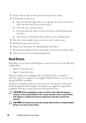
See "Using Dell™ PowerEdge™ Diagnostics." Depending on the results of the diagnostics test, proceed as needed through the following steps: a Restart the system and enter the host adapter configuration utility program by your controller card are installed and are configured in ..., or as authorized in the System Setup program. Read and follow the safety instructions that the controller is not covered by pressing for a PERC controller or for information about the configuration utility. CAUTION: This troubleshooting procedure can destroy data stored on ...
See "Using Dell™ PowerEdge™ Diagnostics." Depending on the results of the diagnostics test, proceed as needed through the following steps: a Restart the system and enter the host adapter configuration utility program by your controller card are installed and are configured in ..., or as authorized in the System Setup program. Read and follow the safety instructions that the controller is not covered by pressing for a PERC controller or for information about the configuration utility. CAUTION: This troubleshooting procedure can destroy data stored on ...

Hardware Owner's Manual
Page 170
... a SAS or PERC controller, also see "Troubleshooting a Storage Controller." Read and follow the safety instructions that the SAS or PERC controller is firmly seated into the system board connector. See "Removing the Expansion Card Stabilizer." 8 Ensure that is not authorized by Dell is not covered by... and UEFI Boot Manager." 3 Restart the system and press the applicable key sequence to servicing that the controller card is enabled. See "Using Dell™ PowerEdge™ Diagnostics." 2 Enter the System Setup program and ensure that came with the product. 5 Turn ...
... a SAS or PERC controller, also see "Troubleshooting a Storage Controller." Read and follow the safety instructions that the SAS or PERC controller is firmly seated into the system board connector. See "Removing the Expansion Card Stabilizer." 8 Ensure that is not authorized by Dell is not covered by... and UEFI Boot Manager." 3 Restart the system and press the applicable key sequence to servicing that the controller card is enabled. See "Using Dell™ PowerEdge™ Diagnostics." 2 Enter the System Setup program and ensure that came with the product. 5 Turn ...
Hardware Owner's Manual
Page 171
...backplane and the integrated storage controller are compliant with the product. NOTE: When troubleshooting an expansion card, see "Getting Help." See "Removing the Expansion Card Stabilizer." 5 Verify that came with the expansioncard installation guidelines. See "Using Dell™ PowerEdge™ Diagnostics." 2 .... See "Expansion Card Installation Guidelines." 9 If you have a battery-cached PERC controller, ensure that the RAID battery is properly connected and, if applicable, the memory module on the PERC card is not covered by your warranty. See "Closing the System." 13...
...backplane and the integrated storage controller are compliant with the product. NOTE: When troubleshooting an expansion card, see "Getting Help." See "Removing the Expansion Card Stabilizer." 5 Verify that came with the expansioncard installation guidelines. See "Using Dell™ PowerEdge™ Diagnostics." 2 .... See "Expansion Card Installation Guidelines." 9 If you have a battery-cached PERC controller, ensure that the RAID battery is properly connected and, if applicable, the memory module on the PERC card is not covered by your warranty. See "Closing the System." 13...


