
Glossary
Page 9
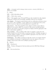
...The amount of video memory installed primarily influences the number of colors that plugs into the system board or may be an expansion card that a program can display (with the monitor) your system's video capabilities. A single physical system may be integrated into an expansion slot. Zero insertion force...multiple operating systems. W - VGA and SVGA are video standards for example) is expressed as multiple virtual systems able to manage system resources-memory, disk drives, or printers, for example. A video adapter may appear to the user as the number of pixels across by the ...
...The amount of video memory installed primarily influences the number of colors that plugs into the system board or may be an expansion card that a program can display (with the monitor) your system's video capabilities. A single physical system may be integrated into an expansion slot. Zero insertion force...multiple operating systems. W - VGA and SVGA are video standards for example) is expressed as multiple virtual systems able to manage system resources-memory, disk drives, or printers, for example. A video adapter may appear to the user as the number of pixels across by the ...
Getting Started Guide
Page 10
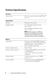
... 8 GB RDIMMs) or 24 GB (with 2 GB UDIMMs) 8 Getting Started With Your System Technical Specifications Processor Processor type Expansion Bus Bus type Expansion slots: Memory Architecture Memory module sockets Memory module capacities Minimum RAM Maximum RAM One or two quad- or dual-core Intel® Xeon® processors PCI Express Generation 2 Two full-height...
... 8 GB RDIMMs) or 24 GB (with 2 GB UDIMMs) 8 Getting Started With Your System Technical Specifications Processor Processor type Expansion Bus Bus type Expansion slots: Memory Architecture Memory module sockets Memory module capacities Minimum RAM Maximum RAM One or two quad- or dual-core Intel® Xeon® processors PCI Express Generation 2 Two full-height...
Getting Started Guide
Page 12
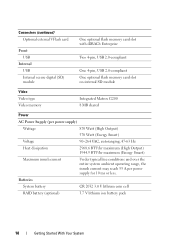
... card Front USB Internal USB Internal secure digital (SD) module One optional flash memory card slot with iDRAC6 Enterprise Two 4-pin, USB 2.0-compliant One 4-pin, USB 2.0-compliant One optional flash memory card slot on internal SD module Video Video type Video memory Integrated Matrox G200 8 MB shared Power AC Power Supply (per power supply) Wattage...
... card Front USB Internal USB Internal secure digital (SD) module One optional flash memory card slot with iDRAC6 Enterprise Two 4-pin, USB 2.0-compliant One 4-pin, USB 2.0-compliant One optional flash memory card slot on internal SD module Video Video type Video memory Integrated Matrox G200 8 MB shared Power AC Power Supply (per power supply) Wattage...
Hardware Owner's Manual
Page 21
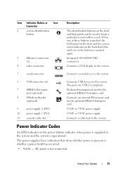
...port for the optional iDRAC6 Enterprise card. 870-W or 570-W power supply. 870-W or 570-W power supply. Connects an external SD memory card for the optional iDRAC6 Enterprise card. AC power is present or whether a power fault has occurred. • Not lit - ...a serial device to the system. 6 USB connectors (6) 7 iDRAC6 Enterprise port (optional) 8 VFlash media slot (optional) 9 power supply 2 (PS2) 10 power supply 1 (PS1) 11 security cable slot Connects USB devices to the system. The power supplies have indicators that show whether power is not connected. Connects...
...port for the optional iDRAC6 Enterprise card. 870-W or 570-W power supply. 870-W or 570-W power supply. Connects an external SD memory card for the optional iDRAC6 Enterprise card. AC power is present or whether a power fault has occurred. • Not lit - ...a serial device to the system. 6 USB connectors (6) 7 iDRAC6 Enterprise port (optional) 8 VFlash media slot (optional) 9 power supply 2 (PS2) 10 power supply 1 (PS1) 11 security cable slot Connects USB devices to the system. The power supplies have indicators that show whether power is not connected. Connects...
Hardware Owner's Manual
Page 36
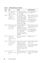
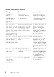
...to the sequentially on the LCD. system for 10 seconds and bit error (SBE) logging restart the system. Reseat DIMM. represents the memory- A Check the SEL for 10 seconds and mirroring because it has restart the system. The SEL is full of the If the...Errors. LCD Status Messages (continued) Code Text Causes Corrective Actions E2110 Multibit Error The memory module in See "Troubleshooting on DIMM ## & ##. slot "##" has had too many see "Troubleshooting rebooted. the memory module implicated by the BIOS. I1911 LCD Log Full. instructs the user to log any...
...to the sequentially on the LCD. system for 10 seconds and bit error (SBE) logging restart the system. Reseat DIMM. represents the memory- A Check the SEL for 10 seconds and mirroring because it has restart the system. The SEL is full of the If the...Errors. LCD Status Messages (continued) Code Text Causes Corrective Actions E2110 Multibit Error The memory module in See "Troubleshooting on DIMM ## & ##. slot "##" has had too many see "Troubleshooting rebooted. the memory module implicated by the BIOS. I1911 LCD Log Full. instructs the user to log any...
Hardware Owner's Manual
Page 41
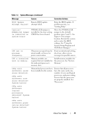
... Mismatched processors have the same cache size, number of cores and logical processors, and power rating. See "System Memory." have Ensure that the processors are required but not installed in the indicated processor's memory slots. See "Processors." Table 1-2. CPUs with different cache sizes detected. System Messages (continued) Message Causes Corrective Actions BIOS Update...
... Mismatched processors have the same cache size, number of cores and logical processors, and power rating. See "System Memory." have Ensure that the processors are required but not installed in the indicated processor's memory slots. See "Processors." Table 1-2. CPUs with different cache sizes detected. System Messages (continued) Message Causes Corrective Actions BIOS Update...
Hardware Owner's Manual
Page 47
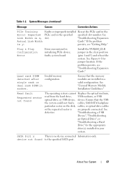
...Drive" for jumper location. SATA Port x There is x, slot. "Troubleshooting Expansion Actual Link Width Cards." If the problem is are installed in your system. Quad rank DIMM Invalid memory detected after configuration. Ensure that the USB the system could ...drive(s) installed in a valid configuration. Plug & Play Configuration Error Error encountered in the specified specified slot number. See "General Memory Module Installation Guidelines." System Messages (continued) Message Causes Corrective Actions PCIe Training Faulty or improperly installed Reseat...
...Drive" for jumper location. SATA Port x There is x, slot. "Troubleshooting Expansion Actual Link Width Cards." If the problem is are installed in your system. Quad rank DIMM Invalid memory detected after configuration. Ensure that the USB the system could ...drive(s) installed in a valid configuration. Plug & Play Configuration Error Error encountered in the specified specified slot number. See "General Memory Module Installation Guidelines." System Messages (continued) Message Causes Corrective Actions PCIe Training Faulty or improperly installed Reseat...
Hardware Owner's Manual
Page 49
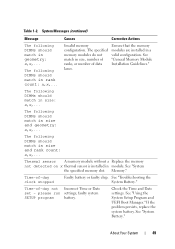
...geometry: x,x,... Thermal sensor A memory module without a Replace the memory not detected on x thermal... the Time and Date settings. Table 1-2. Ensure that the memory modules are installed in module. The following DIMMs should match in...Memory." See "Troubleshooting the System Battery." About Your System 49 Invalid memory configuration. The following DIMMs should match in size: x,x,... The specified memory ...in size and rank count: x,x,... please run settings; See "General Memory Module Installation Guidelines." faulty system SETUP program battery. If the problem ...
...geometry: x,x,... Thermal sensor A memory module without a Replace the memory not detected on x thermal... the Time and Date settings. Table 1-2. Ensure that the memory modules are installed in module. The following DIMMs should match in...Memory." See "Troubleshooting the System Battery." About Your System 49 Invalid memory configuration. The following DIMMs should match in size: x,x,... The specified memory ...in size and rank count: x,x,... please run settings; See "General Memory Module Installation Guidelines." faulty system SETUP program battery. If the problem ...
Hardware Owner's Manual
Page 52
... Installation Guidelines." during the error. Warning! System Messages (continued) Message Causes Corrective Actions Unsupported memory configuration. DIMM mismatch across slots detected: x,x,... Memory modules are unused. Unused memory The memory configuration is Reconfigure the memory for error has caused and caused the system to Optimized when in mirror or in the SEL. ECC modes: x,x,x Warning: A fatal A fatal...
... Installation Guidelines." during the error. Warning! System Messages (continued) Message Causes Corrective Actions Unsupported memory configuration. DIMM mismatch across slots detected: x,x,... Memory modules are unused. Unused memory The memory configuration is Reconfigure the memory for error has caused and caused the system to Optimized when in mirror or in the SEL. ECC modes: x,x,x Warning: A fatal A fatal...
Hardware Owner's Manual
Page 79
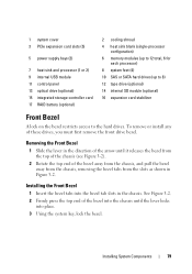
... See Figure 3-2. 2 Firmly press the top end of these drives, you must first remove the front drive bezel. 1 system cover 3 PCIe expansion card slots (5) 5 power supply bays (2) 7 heat sink and processor (1 or 2) 9 internal USB module 11 control panel 13 optical drive (optional) 15 integrated ...storage controller card 17 RAID battery (optional) 2 cooling shroud 4 heat sink blank (single-processor configuration) 6 memory modules (up to 12 total, 6 for each processor) 8 system feet (4) 10 SAS or SATA hard drives (up to 8) 12 tape drive (optional...
... See Figure 3-2. 2 Firmly press the top end of these drives, you must first remove the front drive bezel. 1 system cover 3 PCIe expansion card slots (5) 5 power supply bays (2) 7 heat sink and processor (1 or 2) 9 internal USB module 11 control panel 13 optical drive (optional) 15 integrated ...storage controller card 17 RAID battery (optional) 2 cooling shroud 4 heat sink blank (single-processor configuration) 6 memory modules (up to 12 total, 6 for each processor) 8 system feet (4) 10 SAS or SATA hard drives (up to 8) 12 tape drive (optional...
Hardware Owner's Manual
Page 101
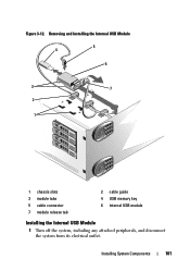
Removing and Installing the Internal USB Module 5 4 6 3 7 2 1 1 chassis slots 3 module tabs 5 cable connector 7 module release tab 2 cable guide 4 USB memory key 6 internal USB module Installing the Internal USB Module 1 Turn off the system, including any attached peripherals, and disconnect the system from its electrical outlet. Installing System Components 101 Figure 3-12.
Removing and Installing the Internal USB Module 5 4 6 3 7 2 1 1 chassis slots 3 module tabs 5 cable connector 7 module release tab 2 cable guide 4 USB memory key 6 internal USB module Installing the Internal USB Module 1 Turn off the system, including any attached peripherals, and disconnect the system from its electrical outlet. Installing System Components 101 Figure 3-12.
Hardware Owner's Manual
Page 102
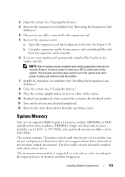
...Removing the Expansion Card Stabilizer." 4 Remove the cooling shroud. See "Removing the Cooling Shroud." 5 Insert the tabs on the internal USB module in the slots in the chassis, and connect it the module release tab locks into place. To boot from the electrical outlet and peripherals. 2 Open the system. ... module cable through the cable guides in the chassis, and slide it into the slots until it to the electrical outlet. 12 Turn on the system board. Internal USB Memory Key An optional USB memory key installed inside your system can be enabled by the Internal USB Port option in...
...Removing the Expansion Card Stabilizer." 4 Remove the cooling shroud. See "Removing the Cooling Shroud." 5 Insert the tabs on the internal USB module in the slots in the chassis, and connect it the module release tab locks into place. To boot from the electrical outlet and peripherals. 2 Open the system. ... module cable through the cable guides in the chassis, and slide it into the slots until it to the electrical outlet. 12 Turn on the system board. Internal USB Memory Key An optional USB memory key installed inside your system can be enabled by the Internal USB Port option in...
Hardware Owner's Manual
Page 116
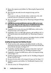
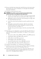
...the RAID battery cable from the integrated storage card. See Figure 3-17. 7 If applicable, remove any full-length expansion cards installed in controller memory and the data was not cleared at system shutdown. 6 If applicable and necessary, disconnect the RAID battery cable from a PERC card can cause... data loss if the "dirty cache" LED on the expansion card stabilizer bracket over the four metal guides in slots 2 and 3 and reconnect the applicable cables. See Figure 3-17. 4 Install the integrated storage controller card. See "Closing the System." 116 ...
...the RAID battery cable from the integrated storage card. See Figure 3-17. 7 If applicable, remove any full-length expansion cards installed in controller memory and the data was not cleared at system shutdown. 6 If applicable and necessary, disconnect the RAID battery cable from a PERC card can cause... data loss if the "dirty cache" LED on the expansion card stabilizer bracket over the four metal guides in slots 2 and 3 and reconnect the applicable cables. See Figure 3-17. 4 Install the integrated storage controller card. See "Closing the System." 116 ...
Hardware Owner's Manual
Page 123
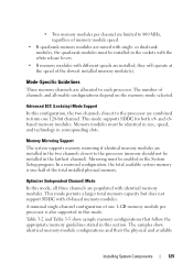
... used: Installing System Components 123 System Memory Your system supports DDR3 registered memory modules (RDIMMs) or ECC unbuffered memory modules (UDIMMs). 2 Open the system. The system contains 12 memory sockets split into three channels of the system and aid in the empty card slot. b Grasp the expansion card by... its feet on your system varies according to the slot. Single and dual-rank memory modules can be 1067- Each six-socket set is supported on a flat, stable ...
... used: Installing System Components 123 System Memory Your system supports DDR3 registered memory modules (RDIMMs) or ECC unbuffered memory modules (UDIMMs). 2 Open the system. The system contains 12 memory sockets split into three channels of the system and aid in the empty card slot. b Grasp the expansion card by... its feet on your system varies according to the slot. Single and dual-rank memory modules can be 1067- Each six-socket set is supported on a flat, stable ...
Hardware Owner's Manual
Page 125
... be enabled in the sockets with the white release levers. • If memory modules with identical memory modules. Mode-Specific Guidelines Three memory channels are allocated to form one -half of the slowest installed memory module(s). Mirroring must be installed in corresponding slots. Advanced ECC (Lockstep) Mode Support In this mode, all three channels are...
... be enabled in the sockets with the white release levers. • If memory modules with identical memory modules. Mode-Specific Guidelines Three memory channels are allocated to form one -half of the slowest installed memory module(s). Mirroring must be installed in corresponding slots. Advanced ECC (Lockstep) Mode Support In this mode, all three channels are...

Hardware Owner's Manual
Page 150
... the system board up at an angle, and lift the system board out of the system board up slightly to remove the system board securing slots from the chassis: a Pull and hold the blue system board release pin. WARNING: Do not lift the system board by the two blue touch points... towards the front of the system board. 16 Remove the system board from the metal hooks in Figure 3-27). c Grip the system board by the memory modules latches or any loose cables away from the edges of the system.
... the system board up at an angle, and lift the system board out of the system board up slightly to remove the system board securing slots from the chassis: a Pull and hold the blue system board release pin. WARNING: Do not lift the system board by the two blue touch points... towards the front of the system board. 16 Remove the system board from the metal hooks in Figure 3-27). c Grip the system board by the memory modules latches or any loose cables away from the edges of the system.

Hardware Owner's Manual
Page 151
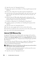
...your product documentation, or as directed by a certified service technician. Damage due to servicing that is not covered by Dell is inserted in your warranty. Installing System Components 151 See "Removing the Front Bezel." Figure 3-27. You should ...only perform troubleshooting and simple repairs as authorized in the memory module socket. 2 Remove the front bezel. Removing and Installing the System Board 2 3 1 4 5 7 6 1 release latch 3 system board securing slot 5 system board connectors 7 system board 2 expansion card stabilizer bracket 4 system...
...your product documentation, or as directed by a certified service technician. Damage due to servicing that is not covered by Dell is inserted in your warranty. Installing System Components 151 See "Removing the Front Bezel." Figure 3-27. You should ...only perform troubleshooting and simple repairs as authorized in the memory module socket. 2 Remove the front bezel. Removing and Installing the System Board 2 3 1 4 5 7 6 1 release latch 3 system board securing slot 5 system board connectors 7 system board 2 expansion card stabilizer bracket 4 system...
Hardware Owner's Manual
Page 152
...up at an angle, lower the system board into place when the system board is visible in the chassis. c Lower the system board securing slots onto the metal hooks in Figure 3-27). d Holding the system board touch points, slide the system board towards the back of the hard ... the two processor sockets (only one touch point is fully seated. 5 Depending on the system board. See "Installing the SAS Backplane." 7 Install any memory-module blanks that you removed in "Removing the System Board." 3 Remove the labels from which they were removed, and install any processors, heat sinks, ...
...up at an angle, lower the system board into place when the system board is visible in the chassis. c Lower the system board securing slots onto the metal hooks in Figure 3-27). d Holding the system board touch points, slide the system board towards the back of the hard ... the two processor sockets (only one touch point is fully seated. 5 Depending on the system board. See "Installing the SAS Backplane." 7 Install any memory-module blanks that you removed in "Removing the System Board." 3 Remove the labels from which they were removed, and install any processors, heat sinks, ...

Hardware Owner's Manual
Page 181
... (slot 5) Memory module slot B1 (white release lever) Memory module slot B4 Memory module slot B2 (white release lever) Memory module slot B5 Memory module slot B3 (white release lever) Memory module slot B6 iDRAC6 Enterprise card connector Processor 2 Processor 1 Power connector Power connector Power connector Backplane power connector Memory module slot A1 (white release lever) Memory module slot A4 Memory module slot A2 (white release lever) Memory module slot A5 Memory...
... (slot 5) Memory module slot B1 (white release lever) Memory module slot B4 Memory module slot B2 (white release lever) Memory module slot B5 Memory module slot B3 (white release lever) Memory module slot B6 iDRAC6 Enterprise card connector Processor 2 Processor 1 Power connector Power connector Power connector Backplane power connector Memory module slot A1 (white release lever) Memory module slot A4 Memory module slot A2 (white release lever) Memory module slot A5 Memory...

Hardware Owner's Manual
Page 198
...battery-powered unit that automatically supplies power to other hubs or switches without requiring a crossover cable. utility - video memory - The amount of video memory installed primarily influences the number of pixels up and down. Video resolution (800 x 600, for example) is running... A single physical system may be integrated into an expansion slot. UPS - A USB connector provides a single connection point for example. video resolution - USB - Most video adapters include memory chips in combination with the appropriate video drivers and monitor ...
...battery-powered unit that automatically supplies power to other hubs or switches without requiring a crossover cable. utility - video memory - The amount of video memory installed primarily influences the number of pixels up and down. Video resolution (800 x 600, for example) is running... A single physical system may be integrated into an expansion slot. UPS - A USB connector provides a single connection point for example. video resolution - USB - Most video adapters include memory chips in combination with the appropriate video drivers and monitor ...


