

Glossary
Page 3
...,824 bytes. host adapter - Hz - Integrated Dell Remote Access Controller. IP - Fahrenheit. The Microsoft® Windows® operating systems can be defined as x horizontal by y vertical pixels by MS-DOS to insert or install a device, typically a hard drive or an ... between the system's bus and the peripheral device, typically a storage device. expansion-card connector - A connector on and running. F - flash memory - A type of file storage. Gravities. Gigabit(s); 1024 megabits or 1,073,741,824 bits. A controller that uses the Internet SCSI protocol. ...
...,824 bytes. host adapter - Hz - Integrated Dell Remote Access Controller. IP - Fahrenheit. The Microsoft® Windows® operating systems can be defined as x horizontal by y vertical pixels by MS-DOS to insert or install a device, typically a hard drive or an ... between the system's bus and the peripheral device, typically a storage device. expansion-card connector - A connector on and running. F - flash memory - A type of file storage. Gravities. Gigabit(s); 1024 megabits or 1,073,741,824 bits. A controller that uses the Internet SCSI protocol. ...

Glossary
Page 5
... MB - Megabytes per second. A specific location, usually expressed as integrated memory (ROM and RAM) and add-in memory modules (DIMMs). memory module - memory - memory key - mirroring - Managed object format is installed or integrated in the system's RAM. A device that is an ASCII file...However, when referring to serve specific storage needs. MBR - Master boot record. Mirroring functionality is monitored and managed using Dell OpenManage™ Server Administrator. Millimeter(s). Media Access Control address. A managed system is any system that are optimized to...
... MB - Megabytes per second. A specific location, usually expressed as integrated memory (ROM and RAM) and add-in memory modules (DIMMs). memory module - memory - memory key - mirroring - Managed object format is installed or integrated in the system's RAM. A device that is an ASCII file...However, when referring to serve specific storage needs. MBR - Master boot record. Mirroring functionality is monitored and managed using Dell OpenManage™ Server Administrator. Millimeter(s). Media Access Control address. A managed system is any system that are optimized to...

Glossary
Page 8
...is running. When such devices are video standards for operation. Uninterruptible power supply. See memory key. 8 See RAM. uplink port - USB memory key - striping - VGA and SVGA are connected in an array. System Setup program... - A BIOS-based program that allows a network manager to I/O devices. USB - Universal Serial Bus. system board - SMP - Some devices (such as password protection. U-DIMM - Used to describe a system that tells a system what hardware is installed...
...is running. When such devices are video standards for operation. Uninterruptible power supply. See memory key. 8 See RAM. uplink port - USB memory key - striping - VGA and SVGA are connected in an array. System Setup program... - A BIOS-based program that allows a network manager to I/O devices. USB - Universal Serial Bus. system board - SMP - Some devices (such as password protection. U-DIMM - Used to describe a system that tells a system what hardware is installed...
Glossary
Page 9
.... ZIF - Zero insertion force. 9 VGA and SVGA are video standards for example. video memory - video resolution - Watt(s). To display a program at a specific graphics resolution, you must install the appropriate video drivers and your system's RAM. utility - VDC - A video adapter may... be an expansion card that plugs into an expansion slot. The amount of video memory installed primarily influences the number of pixels up and down. Video resolution (800 x 600, for example) is expressed as multiple virtual ...
.... ZIF - Zero insertion force. 9 VGA and SVGA are video standards for example. video memory - video resolution - Watt(s). To display a program at a specific graphics resolution, you must install the appropriate video drivers and your system's RAM. utility - VDC - A video adapter may... be an expansion card that plugs into an expansion slot. The amount of video memory installed primarily influences the number of pixels up and down. Video resolution (800 x 600, for example) is expressed as multiple virtual ...
Information Update - Intel Xeon 5600 Series Processors
Page 3
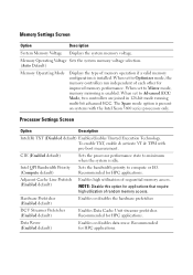
.... DCU Streamer Prefetcher (Enabled default) Enables Data Cache Unit streamer prefetcher. Memory Operating Voltage Sets the system memory voltage selection. (Auto Default) Memory Operating Mode Displays the type of each other for HPC applications. When set to minimum when the system is installed. NOTE: Disable this option for HPC applications. To enable TXT, enable...
.... DCU Streamer Prefetcher (Enabled default) Enables Data Cache Unit streamer prefetcher. Memory Operating Voltage Sets the system memory voltage selection. (Auto Default) Memory Operating Mode Displays the type of each other for HPC applications. When set to minimum when the system is installed. NOTE: Disable this option for HPC applications. To enable TXT, enable...
Deploying UEFI-Aware Operating Systems on Dell PowerEdge Servers
Page 10
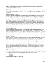
... applications to create a boot option in a disk. Data partitions (non‐system partitions) can be able to boot to another Dell system, the system uses the copy of the operating system boot option on the second system. Otherwise different disks will eliminate the inherent...on the hard disk with the operating system. When an operating system installer executes, it creates a boot option for the operating system in order to have the boot option in its non‐volatile memory. Page 8 Limitations This section explains potential problems which contains the operating...
... applications to create a boot option in a disk. Data partitions (non‐system partitions) can be able to boot to another Dell system, the system uses the copy of the operating system boot option on the second system. Otherwise different disks will eliminate the inherent...on the hard disk with the operating system. When an operating system installer executes, it creates a boot option for the operating system in order to have the boot option in its non‐volatile memory. Page 8 Limitations This section explains potential problems which contains the operating...
Information Update
Page 1
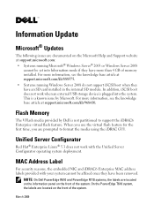
... For security reasons, the embedded NIC and iDRAC6 Enterprise MAC address labels provided with the Unified Server Configurator operating system deployment. On the PowerEdge T610 system, the labels are located on the information panel on the front of the system. In addition, iSCSI boot does not work with... use the virtual flash feature for the first time, you are prompted to support the iDRAC6 Enterprise virtual flash feature. NOTE: On Dell PowerEdge R610 and PowerEdge R710 systems, the labels are located on the front of memory installed. For more than 4 GB of the system. Flash...
... For security reasons, the embedded NIC and iDRAC6 Enterprise MAC address labels provided with the Unified Server Configurator operating system deployment. On the PowerEdge T610 system, the labels are located on the information panel on the front of the system. In addition, iSCSI boot does not work with... use the virtual flash feature for the first time, you are prompted to support the iDRAC6 Enterprise virtual flash feature. NOTE: On Dell PowerEdge R610 and PowerEdge R710 systems, the labels are located on the front of memory installed. For more than 4 GB of the system. Flash...
Getting Started Guide
Page 10
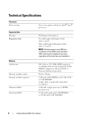
... and 5) NOTE: All slots support up to 25W, but a maximum of two 25W cards and three 15W cards may be installed at any time, regardless of the slots they are installed in. 800, 1066, or 1333 MHz DDR3 registered or unbuffered Error Correcting Code (ECC) DIMMs. Support for Advanced ECC or... Memory Optimized operation. and 2 GB, 4 GB, or 8 GB RDIMMs (single, dual, or quad-rank, dependent on capacity) 1 GB with a single ...
... and 5) NOTE: All slots support up to 25W, but a maximum of two 25W cards and three 15W cards may be installed at any time, regardless of the slots they are installed in. 800, 1066, or 1333 MHz DDR3 registered or unbuffered Error Correcting Code (ECC) DIMMs. Support for Advanced ECC or... Memory Optimized operation. and 2 GB, 4 GB, or 8 GB RDIMMs (single, dual, or quad-rank, dependent on capacity) 1 GB with a single ...
Getting Started Guide
Page 11
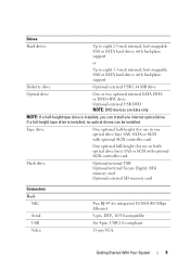
... internal SATA DVD, or DVD+RW drive Optional external USB DVD NOTE: DVD devices are data only NOTE: If a half-height tape drive is installed, no optical drives can install one optical drive bay) SAS, SATA or SCSI with optional SCSI controller card. If a full-height tape drive is...DTE, 16550-compatible Six 4-pin, USB 2.0-compliant 15-pin VGA Getting Started With Your System 9 Flash drive Optional internal USB Optional internal Secure Digital (SD) memory card Optional external SD memory card Connectors Back NIC Serial USB Video Two RJ-45 for use in one internal optical drive.
... internal SATA DVD, or DVD+RW drive Optional external USB DVD NOTE: DVD devices are data only NOTE: If a half-height tape drive is installed, no optical drives can install one optical drive bay) SAS, SATA or SCSI with optional SCSI controller card. If a full-height tape drive is...DTE, 16550-compatible Six 4-pin, USB 2.0-compliant 15-pin VGA Getting Started With Your System 9 Flash drive Optional internal USB Optional internal Secure Digital (SD) memory card Optional external SD memory card Connectors Back NIC Serial USB Video Two RJ-45 for use in one internal optical drive.
Hardware Owner's Manual
Page 7
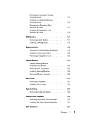
... Battery 117 Removing a RAID Battery 117 Installing a RAID Battery 118 Expansion Cards 118 Expansion Card Installation Guidelines 119 Installing an Expansion Card 120 Removing an Expansion Card 122 System Memory 123 General Memory Module Installation Guidelines 124 Mode-Specific Guidelines 125 Installing Memory Modules 128 Removing Memory Modules 130 Processors 131 Removing a Processor 131 Installing a Processor 134 System Battery 136...
... Battery 117 Removing a RAID Battery 117 Installing a RAID Battery 118 Expansion Cards 118 Expansion Card Installation Guidelines 119 Installing an Expansion Card 120 Removing an Expansion Card 122 System Memory 123 General Memory Module Installation Guidelines 124 Mode-Specific Guidelines 125 Installing Memory Modules 128 Removing Memory Modules 130 Processors 131 Removing a Processor 131 Installing a Processor 134 System Battery 136...
Hardware Owner's Manual
Page 33
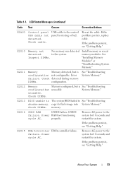
... AC. Remove AC power to the system for 10 seconds and restart the system. Reseat the cable. See "Installing Memory Modules" or "Troubleshooting System Memory." E2011 Memory Memory detected, but unusable. properly. Check cable. E2010 Memory not No memory was detected detected. failure. E2014 CMOS RAM CMOS failure. Remove AC power to the system for 10 seconds...
... AC. Remove AC power to the system for 10 seconds and restart the system. Reseat the cable. See "Installing Memory Modules" or "Troubleshooting System Memory." E2011 Memory Memory detected, but unusable. properly. Check cable. E2010 Memory not No memory was detected detected. failure. E2014 CMOS RAM CMOS failure. Remove AC power to the system for 10 seconds...
Hardware Owner's Manual
Page 41
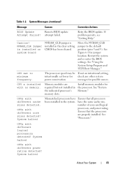
... (pins 3 and 5). CPUs with different core sizes detected! CPUs with different cache sizes detected. See "Processors." attempt failed. Move the NVRAM_CLR jumper to minimum frequency. Install memory modules for check any other system power conservation. CMOS has been cleared. System halted About Your System 41 If problem persists, see "Getting Help...
... (pins 3 and 5). CPUs with different core sizes detected! CPUs with different cache sizes detected. See "Processors." attempt failed. Move the NVRAM_CLR jumper to minimum frequency. Install memory modules for check any other system power conservation. CMOS has been cleared. System halted About Your System 41 If problem persists, see "Getting Help...

Hardware Owner's Manual
Page 59
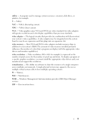
... Figure 2-1. Sets the date on the system's internal clock. Displays information related to installed memory. NOTE: The System Setup program defaults are listed under their respective options in the following sections, where applicable. Option System Time System Date Memory Settings Processor Settings Description Sets the time on the system's internal calendar. Using the...
... Figure 2-1. Sets the date on the system's internal clock. Displays information related to installed memory. NOTE: The System Setup program defaults are listed under their respective options in the following sections, where applicable. Option System Time System Date Memory Settings Processor Settings Description Sets the time on the system's internal calendar. Using the...
Hardware Owner's Manual
Page 125
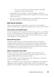
The number of the slowest installed memory module(s). Optimizer (Independent Channel) Mode In this mode, all three channels are installed in the two channels closest to the processor are mixed with identical memory modules. and x8based memory modules. Memory Mirroring Support The system supports memory mirroring if identical memory modules are populated with single- Advanced ECC (Lockstep) Mode Support...
The number of the slowest installed memory module(s). Optimizer (Independent Channel) Mode In this mode, all three channels are installed in the two channels closest to the processor are mixed with identical memory modules. and x8based memory modules. Memory Mirroring Support The system supports memory mirroring if identical memory modules are populated with single- Advanced ECC (Lockstep) Mode Support...
Hardware Owner's Manual
Page 128
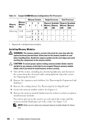
... end of the socket until the memory-module blank pops out of the socket. See Figure 6-1. 5 Remove the memory-module blanks from the sockets in which you intend to install memory in any memory socket that is not occupied. Remove memory-module blanks only if you plan ...to retain any attached peripherals, and disconnect the system from the electrical outlet and peripherals. NOTE: Make sure to install memory modules: Press down . Requires x4- or x8-based memory modules. See "Opening the System." 2 Remove the expansion card stabilizer. See Figure 3-20. Table 3-3. See "Removing...
... end of the socket until the memory-module blank pops out of the socket. See Figure 6-1. 5 Remove the memory-module blanks from the sockets in which you intend to install memory in any memory socket that is not occupied. Remove memory-module blanks only if you plan ...to retain any attached peripherals, and disconnect the system from the electrical outlet and peripherals. NOTE: Make sure to install memory modules: Press down . Requires x4- or x8-based memory modules. See "Opening the System." 2 Remove the expansion card stabilizer. See Figure 3-20. Table 3-3. See "Removing...

Hardware Owner's Manual
Page 130
...down. See "Opening the System." 3 Remove the expansion card stabilizer. See Figure 6-1. 130 Installing System Components The system should have already changed the value to reflect the newly installed memory. 17 If the value is not occupied. See "Removing the Cooling Shroud." 5 Locate ...2 Open the system. CAUTION: To ensure proper system cooling, memory-module blanks must be installed in the system diagnostics. Install a memory-module blank if you are firmly seated in their sockets. 18 Run the system memory test in any peripherals, then connect the system to the electrical...
...down. See "Opening the System." 3 Remove the expansion card stabilizer. See Figure 6-1. 130 Installing System Components The system should have already changed the value to reflect the newly installed memory. 17 If the value is not occupied. See "Removing the Cooling Shroud." 5 Locate ...2 Open the system. CAUTION: To ensure proper system cooling, memory-module blanks must be installed in the system diagnostics. Install a memory-module blank if you are firmly seated in their sockets. 18 Run the system memory test in any peripherals, then connect the system to the electrical...
Hardware Owner's Manual
Page 131
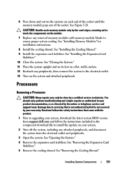
... authorized by Dell is not covered by the card edges, ensuring not to touch the components on the module. 7 Replace any peripherals, then connect the system to upgrading your system, download the latest system BIOS version from the electrical outlet and peripherals. 3 Open the system. See "Installing Memory Modules" for installation instructions. 8 Install the cooling...
... authorized by Dell is not covered by the card edges, ensuring not to touch the components on the module. 7 Replace any peripherals, then connect the system to upgrading your system, download the latest system BIOS version from the electrical outlet and peripherals. 3 Open the system. See "Installing Memory Modules" for installation instructions. 8 Install the cooling...
Hardware Owner's Manual
Page 152
... at an angle, lower the system board into the chassis. See "Installing Memory Modules." 152 Installing System Components b Holding the connector end of the hard drive bays (rack orientation). 4 Install the system board in the chassis: WARNING: Do not lift the system... (tower orientation) or to the INT_USB connector 6 Install the SAS backplane. See "Installing the SAS Backplane." 7 Install any component on your configuration, connect the following cables that were previously removed. See "Installing a Processor." 8 Install the memory modules in "Removing the System Board." See Figure ...
... at an angle, lower the system board into the chassis. See "Installing Memory Modules." 152 Installing System Components b Holding the connector end of the hard drive bays (rack orientation). 4 Install the system board in the chassis: WARNING: Do not lift the system... (tower orientation) or to the INT_USB connector 6 Install the SAS backplane. See "Installing the SAS Backplane." 7 Install any component on your configuration, connect the following cables that were previously removed. See "Installing a Processor." 8 Install the memory modules in "Removing the System Board." See Figure ...
Hardware Owner's Manual
Page 163
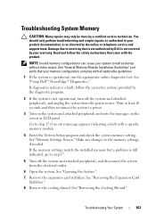
... the Expansion Card Stabilizer." 8 Remove the cooling shroud. If the memory settings match the installed memory but a problem is still indicated, go to power. 3 Turn on the system and attached peripherals and note the messages on the screen or LCD panel. See "Using Dell™ PowerEdge™ Diagnostics." See "Removing the Cooling Shroud." You should...
... the Expansion Card Stabilizer." 8 Remove the cooling shroud. If the memory settings match the installed memory but a problem is still indicated, go to power. 3 Turn on the system and attached peripherals and note the messages on the screen or LCD panel. See "Using Dell™ PowerEdge™ Diagnostics." See "Removing the Cooling Shroud." You should...
Hardware Owner's Manual
Page 164
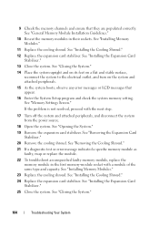
... Cooling Shroud." 12 Replace the expansion card stabilizer. See "Installing the Cooling Shroud." 24 Replace the expansion card stabilizer. 9 Check the memory channels and ensure that appear. 16 Enter the System Setup program and check the system memory setting. See "Installing Memory Modules." 11 Replace the cooling shroud. See "Installing Memory Modules." 23 Replace the cooling shroud.
... Cooling Shroud." 12 Replace the expansion card stabilizer. See "Installing the Cooling Shroud." 24 Replace the expansion card stabilizer. 9 Check the memory channels and ensure that appear. 16 Enter the System Setup program and check the system memory setting. See "Installing Memory Modules." 11 Replace the cooling shroud. See "Installing Memory Modules." 23 Replace the cooling shroud.


