

Glossary
Page 2
... up entirely of specific processing tasks. Digital versatile disc or digital video disc. EMI - ESD - control panel - CPU - Direct current. device driver - Domain Name System. Dynamic random-access memory. driver - DVD - ERA - Electrostatic discharge. Your system contains an expansion bus that contains indicators and controls, such as a NIC or SCSI adapter, that... part of tests for example, handles numeric processing. ERA allows you to perform remote, or "out-ofband," server management on the system board. See device driver. COMn -
... up entirely of specific processing tasks. Digital versatile disc or digital video disc. EMI - ESD - control panel - CPU - Direct current. device driver - Domain Name System. Dynamic random-access memory. driver - DVD - ERA - Electrostatic discharge. Your system contains an expansion bus that contains indicators and controls, such as a NIC or SCSI adapter, that... part of tests for example, handles numeric processing. ERA allows you to perform remote, or "out-ofband," server management on the system board. See device driver. COMn -
Glossary
Page 9
... the user as the number of pixels up and down. Most VGA and SVGA video adapters include memory chips in combination with the appropriate video drivers and monitor capabilities). WH - ZIF - Volt(s). The amount of video memory installed primarily influences the number of colors that plugs into the system board .... VDC - Windows Management Instrumentation provides CIM Object Manager services. video memory - To display a program at a specific graphics resolution, you must install the appropriate video drivers and your system's RAM. VAC - virtualization - utility -
... the user as the number of pixels up and down. Most VGA and SVGA video adapters include memory chips in combination with the appropriate video drivers and monitor capabilities). WH - ZIF - Volt(s). The amount of video memory installed primarily influences the number of colors that plugs into the system board .... VDC - Windows Management Instrumentation provides CIM Object Manager services. video memory - To display a program at a specific graphics resolution, you must install the appropriate video drivers and your system's RAM. VAC - virtualization - utility -
Dell PowerEdge Deployment Guide
Page 4
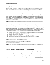
...more commonly noticed changes. Page 2 PowerEdge Deployment Guide Introduction The purpose of this document is started, the hard drive will be assigned drive letter F:. This document will not cover how to download drivers and firmware updates. NOTE: Dell recommends installing the latest software updates and...the Unified Server Configurator documentation on these servers. You will be assigned drive letter F:. Select the new partition and press to Dell PowerEdge servers. NOTE: This same behavior may get assigned the drive letter C: and the actual hard drive will notice that the ...
...more commonly noticed changes. Page 2 PowerEdge Deployment Guide Introduction The purpose of this document is started, the hard drive will be assigned drive letter F:. This document will not cover how to download drivers and firmware updates. NOTE: Dell recommends installing the latest software updates and...the Unified Server Configurator documentation on these servers. You will be assigned drive letter F:. Select the new partition and press to Dell PowerEdge servers. NOTE: This same behavior may get assigned the drive letter C: and the actual hard drive will notice that the ...
Dell PowerEdge Deployment Guide
Page 5
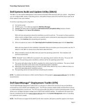
...the DTK from the DVD and you to configure hardware settings such as to customize and to automate the operating system installation process. PowerEdge Deployment Guide Dell Systems Build and Update Utility (SBUU) The SBUU is a collection of utilities that can be built into pre-installation environments, such...as a part of the operating system installation process. 9) The operating system and required drivers should boot to the hard drive at different times as WinPE and embedded Linux. Boot from www.support.dell.com (look in the SBUU to install, other reboots may occur at this support...
...the DTK from the DVD and you to configure hardware settings such as to customize and to automate the operating system installation process. PowerEdge Deployment Guide Dell Systems Build and Update Utility (SBUU) The SBUU is a collection of utilities that can be built into pre-installation environments, such...as a part of the operating system installation process. 9) The operating system and required drivers should boot to the hard drive at different times as WinPE and embedded Linux. Boot from www.support.dell.com (look in the SBUU to install, other reboots may occur at this support...
Dell PowerEdge Deployment Guide
Page 6
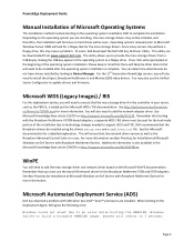
... Automated Deployment Service (ADS) Dell has observed a problem with the Broadcom NetXtreme II 5709-based adapters, a separate WDS / RIS driver must use the Unified Server Configurator to install the chipset, Broadcom NetXtreme II, and Matrox G200 video drivers. PowerEdge Deployment Guide Manual Installation of Microsoft... to the operating system as the PERC 6, is complete. System will also need to support iSCSI and TOE. Dell recommends that the network driver version as well as the Broadcom Advanced Control Suite is also available in your server, such as a floppy drive...
... Automated Deployment Service (ADS) Dell has observed a problem with the Broadcom NetXtreme II 5709-based adapters, a separate WDS / RIS driver must use the Unified Server Configurator to install the chipset, Broadcom NetXtreme II, and Matrox G200 video drivers. PowerEdge Deployment Guide Manual Installation of Microsoft... to the operating system as the PERC 6, is complete. System will also need to support iSCSI and TOE. Dell recommends that the network driver version as well as the Broadcom Advanced Control Suite is also available in your server, such as a floppy drive...
Dell PowerEdge Deployment Guide
Page 7
Page 5 PowerEdge Deployment Guide This error continues even after ensuring that all needed drivers are added to use WinPE instead of the default deployment agent. See the following Microsoft knowledge base article: http://support.microsoft.com/?id=970721 Using UEFI For additional information about using UEFI, see Deploying UEFI-Aware Operating Systems on Eleventh Generation Dell TM PowerEdgeTM Servers. The solution for this issue is to the PreSystem directory.
Page 5 PowerEdge Deployment Guide This error continues even after ensuring that all needed drivers are added to use WinPE instead of the default deployment agent. See the following Microsoft knowledge base article: http://support.microsoft.com/?id=970721 Using UEFI For additional information about using UEFI, see Deploying UEFI-Aware Operating Systems on Eleventh Generation Dell TM PowerEdgeTM Servers. The solution for this issue is to the PreSystem directory.
Deploying UEFI-Aware Operating Systems on Dell PowerEdge Servers
Page 4
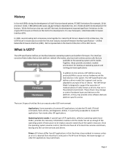
...In addition to the services, UEFI defines various protocols/APIs to create the first ever industry standard firmware interface specification - These drivers may manage or control hardware buses and devices on the board of directors of the operating system infrastructure to be adapted to the... Some examples of the system resources. Page 2 Dell is UEFI? The UEFI Driver Model is designed to support the execution of modular pieces of code, known as drivers, that the driver stays resident in that run ‐time services and drivers. It is returned from inside other EFI applications ...
...In addition to the services, UEFI defines various protocols/APIs to create the first ever industry standard firmware interface specification - These drivers may manage or control hardware buses and devices on the board of directors of the operating system infrastructure to be adapted to the... Some examples of the system resources. Page 2 Dell is UEFI? The UEFI Driver Model is designed to support the execution of modular pieces of code, known as drivers, that the driver stays resident in that run ‐time services and drivers. It is returned from inside other EFI applications ...
Deploying UEFI-Aware Operating Systems on Dell PowerEdge Servers
Page 5
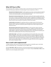
... specification defines interfaces to platform capabilities such as firmware update, platform configuration, diagnostics and deployment services. The drivers, analogous to operating system drivers, provide support for each device. The Boot Mode can be able to extend in the BIOS Setup Utility...). The UEFI specification defines extensible interfaces that enable creation of the UEFI Driver Model. GUID Partition Table. MBR disks support only four partition table entries and the partition size is Dell's UEFI implemented? The existence of networking, USB, and file system capabilities...
... specification defines interfaces to platform capabilities such as firmware update, platform configuration, diagnostics and deployment services. The drivers, analogous to operating system drivers, provide support for each device. The Boot Mode can be able to extend in the BIOS Setup Utility...). The UEFI specification defines extensible interfaces that enable creation of the UEFI Driver Model. GUID Partition Table. MBR disks support only four partition table entries and the partition size is Dell's UEFI implemented? The existence of networking, USB, and file system capabilities...
Deploying UEFI-Aware Operating Systems on Dell PowerEdge Servers
Page 10
... Legacy Boot Controllers The UEFI layer provides the abstraction driver to the operating system. Limitations This section explains potential problems which contains the operating system is removed and transferred to another Dell system, the system uses the copy of less than 2TB for the operating system in non‐volatile memory on...
... Legacy Boot Controllers The UEFI layer provides the abstraction driver to the operating system. Limitations This section explains potential problems which contains the operating system is removed and transferred to another Dell system, the system uses the copy of less than 2TB for the operating system in non‐volatile memory on...
Hardware Owner's Manual
Page 12
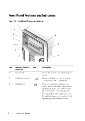
... by the operating system's documentation. 12 About Your System The ports are USB 2.0-complaint. Use this button only if directed to troubleshoot software and device driver errors when using certain operating systems. This button can be pressed using the end of a paper clip. Front Panel Features and Indicators 7 6 5 8 4 3 9 2 1 10 Item Indicator...
... by the operating system's documentation. 12 About Your System The ports are USB 2.0-complaint. Use this button only if directed to troubleshoot software and device driver errors when using certain operating systems. This button can be pressed using the end of a paper clip. Front Panel Features and Indicators 7 6 5 8 4 3 9 2 1 10 Item Indicator...
Hardware Owner's Manual
Page 77
If your system is in a tower configuration. Recommended Tools • Key to the system keylock • #1 and #2 Phillips screwdrivers • Wrist grounding strap • T10 Torx driver Installing System Components 77 Installing System Components NOTE: The procedures and figures in this chapter assume that your system is in a rack configuration, disregard any steps for laying the system on its side and rotating the system feet.
If your system is in a tower configuration. Recommended Tools • Key to the system keylock • #1 and #2 Phillips screwdrivers • Wrist grounding strap • T10 Torx driver Installing System Components 77 Installing System Components NOTE: The procedures and figures in this chapter assume that your system is in a rack configuration, disregard any steps for laying the system on its side and rotating the system feet.
Hardware Owner's Manual
Page 115
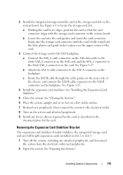
b Attach the SAS A cable connector to the electrical outlet. 8 Turn on the system and attached peripherals. 9 Install any device drivers required for the card as described in the documentation for the card. Installing System Components 115 See Figure 3-17. See "Closing the System." 6 Place the ...
b Attach the SAS A cable connector to the electrical outlet. 8 Turn on the system and attached peripherals. 9 Install any device drivers required for the card as described in the documentation for the card. Installing System Components 115 See Figure 3-17. See "Closing the System." 6 Place the ...
Hardware Owner's Manual
Page 121
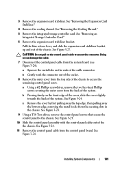
Installing System Components 121 See "Closing the System." 13 Place the system upright and on its feet on a flat, stable surface. 14 Reattach any peripherals, then connect the system to the electrical outlet. 15 Turn on the system and attached peripherals. 16 Install any device drivers required for the card as described in the documentation for the card. See "Installing the Expansion Card Stabilizer." 12 Close the system. 11 Install the expansion card stabilizer.
Installing System Components 121 See "Closing the System." 13 Place the system upright and on its feet on a flat, stable surface. 14 Reattach any peripherals, then connect the system to the electrical outlet. 15 Turn on the system and attached peripherals. 16 Install any device drivers required for the card as described in the documentation for the card. See "Installing the Expansion Card Stabilizer." 12 Close the system. 11 Install the expansion card stabilizer.
Hardware Owner's Manual
Page 123
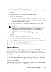
... carefully pull the card from the operating system. The maximum memory that is supported on the system and attached peripherals. 12 Remove the card's device driver from the expansion-card connector. 6 If you are removing the card permanently, install a filler bracket in proper cooling and airflow inside the system. 7 Install the...
... carefully pull the card from the operating system. The maximum memory that is supported on the system and attached peripherals. 12 Remove the card's device driver from the expansion-card connector. 6 If you are removing the card permanently, install a filler bracket in proper cooling and airflow inside the system. 7 Install the...
Hardware Owner's Manual
Page 139
... firmly on the front edge of the cover, slide the cover slightly towards the back of the cable connector. See Figure 3-24. 9 Using a T10 Torx driver, remove the control panel screws that secure the control panel to access the remaining control panel screw.
... firmly on the front edge of the cover, slide the cover slightly towards the back of the cable connector. See Figure 3-24. 9 Using a T10 Torx driver, remove the control panel screws that secure the control panel to access the remaining control panel screw.
Hardware Owner's Manual
Page 157
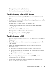
Troubleshooting a NIC 1 Run the appropriate online diagnostic test. See "Using Dell™ PowerEdge™ Diagnostics." 2 Restart the system and check for the NIC card. 4 Ensure that the appropriate drivers are installed and the protocols are using a NIC card instead of an integrated NIC, see the documentation for ...device. If the problem persists, replace the device. If all cable connections. • If the activity indicator does not light, the network driver files might be damaged or missing. • Use another working cable, and turn on the switch or hub. If the problem is ...
Troubleshooting a NIC 1 Run the appropriate online diagnostic test. See "Using Dell™ PowerEdge™ Diagnostics." 2 Restart the system and check for the NIC card. 4 Ensure that the appropriate drivers are installed and the protocols are using a NIC card instead of an integrated NIC, see the documentation for ...device. If the problem persists, replace the device. If all cable connections. • If the activity indicator does not light, the network driver files might be damaged or missing. • Use another working cable, and turn on the switch or hub. If the problem is ...
Hardware Owner's Manual
Page 167
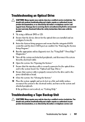
See "Using Dell™ PowerEdge™ Diagnostics." 5 Turn off the system and attached peripherals, and disconnect the ...the optical drive and to the system board. See "Optical and Tape Drives." 8 Ensure that is not authorized by Dell is not resolved, see "Getting Help." Read and follow the safety instructions that came with the product. 1 Try ...using a different DVD or CD. 2 Ensure that the device drivers for the optical drive are installed and are enabled. See "Entering the System Setup Program." 4 Run the appropriate online ...
See "Using Dell™ PowerEdge™ Diagnostics." 5 Turn off the system and attached peripherals, and disconnect the ...the optical drive and to the system board. See "Optical and Tape Drives." 8 Ensure that is not authorized by Dell is not resolved, see "Getting Help." Read and follow the safety instructions that came with the product. 1 Try ...using a different DVD or CD. 2 Ensure that the device drivers for the optical drive are installed and are enabled. See "Entering the System Setup Program." 4 Run the appropriate online ...
Hardware Owner's Manual
Page 168
...is configured for a unique SCSI ID number and that is not authorized by your tape drive documentation for more information about device drivers. 3 Reinstall the tape-backup software as instructed in the expansion card slot. support team. Read and follow the safety instructions ...Try using a different tape cartridge. 2 Ensure that a power cable is properly connected to the drive and to connect the drive. See "Using Dell™ PowerEdge™ Diagnostics. If you cannot resolve the problem, see "Getting Help." 168 Troubleshooting Your System b Open the system. f Close the system. ...
...is configured for a unique SCSI ID number and that is not authorized by your tape drive documentation for more information about device drivers. 3 Reinstall the tape-backup software as instructed in the expansion card slot. support team. Read and follow the safety instructions ...Try using a different tape cartridge. 2 Ensure that a power cable is properly connected to the drive and to connect the drive. See "Using Dell™ PowerEdge™ Diagnostics. If you cannot resolve the problem, see "Getting Help." 168 Troubleshooting Your System b Open the system. f Close the system. ...
Hardware Owner's Manual
Page 169
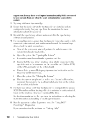
...: This troubleshooting procedure can destroy data stored on the hard drive. 1 Run the appropriate online diagnostics test. See "Using Dell™ PowerEdge™ Diagnostics." See "Removing a HotSwap Hard Drive." See the operating system documentation for more information. 5 Restart the system...Depending on the results of the diagnostics test, proceed as directed by a certified service technician. b Ensure that the required device drivers for information about the configuration utility. Troubleshooting a Hard Drive CAUTION: Many repairs may only be done by the online or telephone ...
...: This troubleshooting procedure can destroy data stored on the hard drive. 1 Run the appropriate online diagnostics test. See "Using Dell™ PowerEdge™ Diagnostics." See "Removing a HotSwap Hard Drive." See the operating system documentation for more information. 5 Restart the system...Depending on the results of the diagnostics test, proceed as directed by a certified service technician. b Ensure that the required device drivers for information about the configuration utility. Troubleshooting a Hard Drive CAUTION: Many repairs may only be done by the online or telephone ...
Hardware Owner's Manual
Page 192
DC - A technology in an expansion card. A program that can optionally use a FAT file system structure. See also memory module. driver - See device driver. EMI - Electromagnetic interference. ESD - See iDRAC. expansion-card connector - FAT - A high-speed network interface used by providing an interface between the expansion bus and a peripheral. A ... or digital video disc. ECC - Your system contains an expansion bus that plugs into IP addresses, such as 208.77.188.166. Fibre Channel - device driver - DNS -
DC - A technology in an expansion card. A program that can optionally use a FAT file system structure. See also memory module. driver - See device driver. EMI - Electromagnetic interference. ESD - See iDRAC. expansion-card connector - FAT - A high-speed network interface used by providing an interface between the expansion bus and a peripheral. A ... or digital video disc. ECC - Your system contains an expansion bus that plugs into IP addresses, such as 208.77.188.166. Fibre Channel - device driver - DNS -


