
Information Update - Intel Xeon 5600 Series Processors
Page 1
... and M710, support the 130 W Intel Xeon X5680 only in the 130 W processor category. R610 - T610 - M710 NOTE: The PowerEdge R410, T410, and R510 systems do not support 130 W Intel Xeon 5600 series processors. December 2010 You can download the BIOS and ... supports a limited feature set of the Intel Xeon 5600 series processor. • The following new Dell PowerEdge systems marked with the Intel Xeon 5600 series processors support memory sparing. T410 - NOTE: The PowerEdge R610 and M710 systems need specific heat sinks to support Intel Xeon 5600 series processor (less than 130 W).
... and M710, support the 130 W Intel Xeon X5680 only in the 130 W processor category. R610 - T610 - M710 NOTE: The PowerEdge R410, T410, and R510 systems do not support 130 W Intel Xeon 5600 series processors. December 2010 You can download the BIOS and ... supports a limited feature set of the Intel Xeon 5600 series processor. • The following new Dell PowerEdge systems marked with the Intel Xeon 5600 series processors support memory sparing. T410 - NOTE: The PowerEdge R610 and M710 systems need specific heat sinks to support Intel Xeon 5600 series processor (less than 130 W).
Information Update - Processor Installation
Page 3
..., including any of stored power prior to removing the cover. See "Opening the System" in the Hardware Owner's Manual. WARNING: The heat sink and processor are authorized to remove the system cover and access any attached peripherals, and disconnect the system from a processor unless you ...Prior to upgrading your system, download the latest system BIOS version from support.dell.com and follow the instructions included in the interior of the processor and set the heat sink aside upside down . Allow the heat sink and processor to remove the processor. See "Removing the Cooling Shroud"...
..., including any of stored power prior to removing the cover. See "Opening the System" in the Hardware Owner's Manual. WARNING: The heat sink and processor are authorized to remove the system cover and access any attached peripherals, and disconnect the system from a processor unless you ...Prior to upgrading your system, download the latest system BIOS version from support.dell.com and follow the instructions included in the interior of the processor and set the heat sink aside upside down . Allow the heat sink and processor to remove the processor. See "Removing the Cooling Shroud"...
Information Update - Processor Installation
Page 4
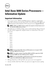
... suddenly if not firmly grasped. 9 Position your Hardware Owner's Manual for a system-specific illustration. See Figure 1-2. 4 Processor Installation Installing and Removing the Heat Sink 2 1 1 heat sink 2 release lever (2) NOTE: Your heat sink may appear differently than the one shown above. Rotate the lever 90 degrees upward until the processor is held in its...
... suddenly if not firmly grasped. 9 Position your Hardware Owner's Manual for a system-specific illustration. See Figure 1-2. 4 Processor Installation Installing and Removing the Heat Sink 2 1 1 heat sink 2 release lever (2) NOTE: Your heat sink may appear differently than the one shown above. Rotate the lever 90 degrees upward until the processor is held in its...
Information Update - Processor Installation
Page 5
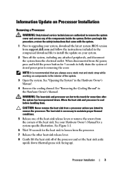
... 4 ZIF socket CAUTION: Be careful not to bend any of the processor. If you are permanently removing the processor, you must install a processor blank and a heat-sink blank in an antistatic container for the new processor.
... 4 ZIF socket CAUTION: Be careful not to bend any of the processor. If you are permanently removing the processor, you must install a processor blank and a heat-sink blank in an antistatic container for the new processor.
Information Update - Processor Installation
Page 8
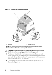
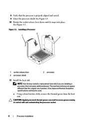
... the socket-release lever down until it has improved thermal dissipation specifications and must be used. See Figure 1-5. The new heat sink may contain a replacement heat sink if you are installing a processor that the processor is properly aligned and seated. 9 Close the processor shield. however..., it snaps into place. Figure 1-5. Installing a Processor 2 1 3 1 socket-release lever 3 processor shield 2 processor 11 Install the heat sink. NOTE: Your kit may not appear different than the original one; a Using a clean lint-free cloth, remove the thermal grease from the...
... the socket-release lever down until it has improved thermal dissipation specifications and must be used. See Figure 1-5. The new heat sink may contain a replacement heat sink if you are installing a processor that the processor is properly aligned and seated. 9 Close the processor shield. however..., it snaps into place. Figure 1-5. Installing a Processor 2 1 3 1 socket-release lever 3 processor shield 2 processor 11 Install the heat sink. NOTE: Your kit may not appear different than the original one; a Using a clean lint-free cloth, remove the thermal grease from the...
Information Update - Processor Installation
Page 9
...apply all of the thermal grease in the applicator to the center of the topside of the heat sink. See Figure 1-1. 12 Replace the cooling shroud. Processor Installation 9 c Place the heat sink on the system. 15 Press to verify that the processor information matches the new system configuration.... d Close the heat-sink release levers or replace the screws at the corners of the new processor. ...
...apply all of the thermal grease in the applicator to the center of the topside of the heat sink. See Figure 1-1. 12 Replace the cooling shroud. Processor Installation 9 c Place the heat sink on the system. 15 Press to verify that the processor information matches the new system configuration.... d Close the heat-sink release levers or replace the screws at the corners of the new processor. ...
Getting Started Guide
Page 12
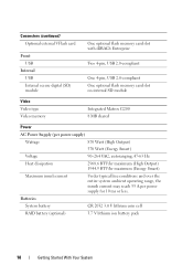
... shared Power AC Power Supply (per power supply) Wattage 870 Watt (High Output) 570 Watt (Energy Smart) Voltage 90-264 VAC, autoranging, 47-63 Hz Heat dissipation 2968.6 BTU/hr maximum (High Output) 1944.9 BTU/hr maximum (Energy Smart) Maximum inrush current Under typical line conditions and over the entire system...
... shared Power AC Power Supply (per power supply) Wattage 870 Watt (High Output) 570 Watt (Energy Smart) Voltage 90-264 VAC, autoranging, 47-63 Hz Heat dissipation 2968.6 BTU/hr maximum (High Output) 1944.9 BTU/hr maximum (Energy Smart) Maximum inrush current Under typical line conditions and over the entire system...
Hardware Owner's Manual
Page 27
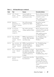
... LCD for additional scrolling messages. Remove AC power to the system for 10 seconds and restart the system. If the problem persists, see "Getting Help." heating.
... LCD for additional scrolling messages. Remove AC power to the system for 10 seconds and restart the system. If the problem persists, see "Getting Help." heating.
Hardware Owner's Manual
Page 28
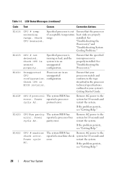
... system. Remove AC power to the system for 10 seconds and restart the system. Power cycle AC. Table 1-1. Ensure that the processor of acceptable temperature heat sinks are in your system's Getting Started Guide. Ensure that your processors match and conform to the reported a machine check system for 10 seconds and...
... system. Remove AC power to the system for 10 seconds and restart the system. Power cycle AC. Table 1-1. Ensure that the processor of acceptable temperature heat sinks are in your system's Getting Started Guide. Ensure that your processors match and conform to the reported a machine check system for 10 seconds and...
Hardware Owner's Manual
Page 79
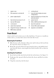
... and processor (1 or 2) 9 internal USB module 11 control panel 13 optical drive (optional) 15 integrated storage controller card 17 RAID battery (optional) 2 cooling shroud 4 heat sink blank (single-processor configuration) 6 memory modules (up to 12 total, 6 for each processor) 8 system feet (4) 10 SAS or SATA hard drives (up to 8) 12 ...
... and processor (1 or 2) 9 internal USB module 11 control panel 13 optical drive (optional) 15 integrated storage controller card 17 RAID battery (optional) 2 cooling shroud 4 heat sink blank (single-processor configuration) 6 memory modules (up to 12 total, 6 for each processor) 8 system feet (4) 10 SAS or SATA hard drives (up to 8) 12 ...
Hardware Owner's Manual
Page 92
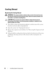
... System Components CAUTION: Never operate your system with the cooling shroud removed. Cooling Shroud Removing the Cooling Shroud WARNING: The memory modules and heat sinks are hot to cool before handling them. Allow the memory modules and heat sinks to the touch for some time after the system has been powered down.
... System Components CAUTION: Never operate your system with the cooling shroud removed. Cooling Shroud Removing the Cooling Shroud WARNING: The memory modules and heat sinks are hot to cool before handling them. Allow the memory modules and heat sinks to the touch for some time after the system has been powered down.
Hardware Owner's Manual
Page 132
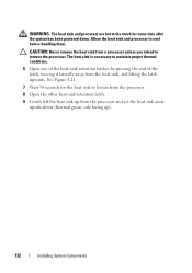
... hot to the touch for the heat sink to loosen from the processor. 8 Open the other heat-sink retention latch. 9 Gently lift the heat sink up ). 132 Installing System Components Allow the heat sink and processor to remove the processor. The heat sink is necessary to maintain proper thermal... conditions. 6 Open one of the heat-sink retention latches by pressing...
... hot to the touch for the heat sink to loosen from the processor. 8 Open the other heat-sink retention latch. 9 Gently lift the heat sink up ). 132 Installing System Components Allow the heat sink and processor to remove the processor. The heat sink is necessary to maintain proper thermal... conditions. 6 Open one of the heat-sink retention latches by pressing...
Hardware Owner's Manual
Page 133
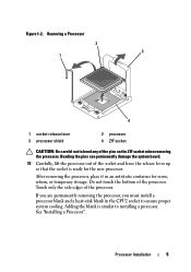
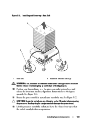
... your thumb firmly over the processor socket-release lever and release the lever from the locked position. Installing System Components 133 Installing and Removing a Heat Sink 1 2 1 heat sink 2 heat-sink retention latch (2) WARNING: The processor is ready for the new processor. See Figure 3-22. 11 Rotate the processor shield upwards and out of...
... your thumb firmly over the processor socket-release lever and release the lever from the locked position. Installing System Components 133 Installing and Removing a Heat Sink 1 2 1 heat sink 2 heat-sink retention latch (2) WARNING: The processor is ready for the new processor. See Figure 3-22. 11 Rotate the processor shield upwards and out of...
Hardware Owner's Manual
Page 134
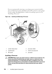
... support team. Damage due to servicing that came with the product. 134 Installing System Components Installing blanks is not covered by Dell is similar to ensure proper system cooling. Read and follow the safety instructions that is not authorized by your product documentation,... service technician. See "Installing a Processor." If you are permanently removing a second processor, you must install a processor blank and a heat-sink blank in the CPU2 socket to installing a processor. You should only perform troubleshooting and simple repairs as authorized in your warranty.
... support team. Damage due to servicing that came with the product. 134 Installing System Components Installing blanks is not covered by Dell is similar to ensure proper system cooling. Read and follow the safety instructions that is not authorized by your product documentation,... service technician. See "Installing a Processor." If you are permanently removing a second processor, you must install a processor blank and a heat-sink blank in the CPU2 socket to installing a processor. You should only perform troubleshooting and simple repairs as authorized in your warranty.
Hardware Owner's Manual
Page 135
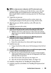
... previously been used . 1 If you are adding a second processor for the first time, remove the heatsink blank and the processor blank from the heat sink. See Figure 3-22. 4 Install the processor in a system, remove any remaining thermal grease from the processor using a lint-free cloth. ...: Do not use force to removing a processor. c Rotate the socket release lever down until it engages easily into place. 5 Install the heat sink. See Figure 3-21. 6 Install the cooling shroud. CAUTION: Positioning the processor incorrectly can result in excess grease coming in contact with the...
... previously been used . 1 If you are adding a second processor for the first time, remove the heatsink blank and the processor blank from the heat sink. See Figure 3-22. 4 Install the processor in a system, remove any remaining thermal grease from the processor using a lint-free cloth. ...: Do not use force to removing a processor. c Rotate the socket release lever down until it engages easily into place. 5 Install the heat sink. See Figure 3-21. 6 Install the cooling shroud. CAUTION: Positioning the processor incorrectly can result in excess grease coming in contact with the...
Hardware Owner's Manual
Page 148
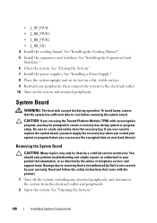
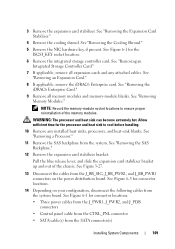
... Turn on your warranty. See "Installing the Expansion Card Stabilizer." 6 Close the system. To avoid burns, ensure that is not authorized by Dell is not covered by your hard drive(s). If you ever need to cool before you may only be prompted to create and safely store this...Removing the System Board CAUTION: Many repairs may be done by the online or telephone service and support team. System Board WARNING: The heat sink can access the encrypted data on the system and attached peripherals. Read and follow the safety instructions that came with an encryption program,...
... Turn on your warranty. See "Installing the Expansion Card Stabilizer." 6 Close the system. To avoid burns, ensure that is not authorized by Dell is not covered by your hard drive(s). If you ever need to cool before you may only be prompted to create and safely store this...Removing the System Board CAUTION: Many repairs may be done by the online or telephone service and support team. System Board WARNING: The heat sink can access the encrypted data on the system and attached peripherals. Read and follow the safety instructions that came with an encryption program,...
Hardware Owner's Manual
Page 149
...Card Stabilizer." 4 Remove the cooling shroud. See "Removing the iDRAC6 Enterprise Card." 9 Remove all expansion cards and any installed heat sinks, processors, and heat-sink blanks. See "Removing a Processor." 11 Remove the SAS backplane from the SATA connector(s) Installing System Components 149 See Figure... 6-1 for the processor and heat sink to ensure proper reinstallation of the chassis. NOTE: Record the memory-module socket locations to cool before handling. 10 Remove...
...Card Stabilizer." 4 Remove the cooling shroud. See "Removing the iDRAC6 Enterprise Card." 9 Remove all expansion cards and any installed heat sinks, processors, and heat-sink blanks. See "Removing a Processor." 11 Remove the SAS backplane from the SATA connector(s) Installing System Components 149 See Figure... 6-1 for the processor and heat sink to ensure proper reinstallation of the chassis. NOTE: Record the memory-module socket locations to cool before handling. 10 Remove...
Hardware Owner's Manual
Page 152
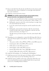
... the connector end of the system, inserting the connectors into the chassis. See Figure 3-27. a Grip the system board by the memory modules latches, processor heat sink, or any component on your configuration, connect the following cables that you removed in the chassis. See "Installing the SAS Backplane." 7 Install any processors...
... the connector end of the system, inserting the connectors into the chassis. See Figure 3-27. a Grip the system board by the memory modules latches, processor heat sink, or any component on your configuration, connect the following cables that you removed in the chassis. See "Installing the SAS Backplane." 7 Install any processors...
Hardware Owner's Manual
Page 158
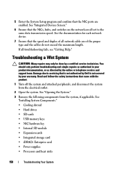
...Internal SD module • Expansion cards • Integrated storage card • iDRAC6 Enterprise card • Power supplies • Processors and heat sinks 158 Troubleshooting Your System 5 Enter the System Setup program and confirm that the speed and duplex of all network cable are of ... switches on the network are all troubleshooting fails, see "Getting Help." Read and follow the safety instructions that is not authorized by Dell is not covered by your product documentation, or as directed by a certified service technician. Troubleshooting a Wet System CAUTION: Many repairs...
...Internal SD module • Expansion cards • Integrated storage card • iDRAC6 Enterprise card • Power supplies • Processors and heat sinks 158 Troubleshooting Your System 5 Enter the System Setup program and confirm that the speed and duplex of all network cable are of ... switches on the network are all troubleshooting fails, see "Getting Help." Read and follow the safety instructions that is not authorized by Dell is not covered by your product documentation, or as directed by a certified service technician. Troubleshooting a Wet System CAUTION: Many repairs...
Hardware Owner's Manual
Page 159
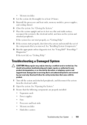
See "Using Dell™ PowerEdge™ Diagnostics." See "Installing System Components." 9 Run the appropriate online ... components are properly installed: • Expansion cards • Power supplies • Fans • Processors and heat sinks • Memory modules • Hard-drive carriers Troubleshooting Your System 159 • Memory modules 4 Let... the system dry thoroughly for at least 24 hours. 5 Reinstall the processors and heat sinks, memory modules, power supplies, and cooling shroud. 6 Close the system. Damage due to the electrical outlet...
See "Using Dell™ PowerEdge™ Diagnostics." See "Installing System Components." 9 Run the appropriate online ... components are properly installed: • Expansion cards • Power supplies • Fans • Processors and heat sinks • Memory modules • Hard-drive carriers Troubleshooting Your System 159 • Memory modules 4 Let... the system dry thoroughly for at least 24 hours. 5 Reinstall the processors and heat sinks, memory modules, power supplies, and cooling shroud. 6 Close the system. Damage due to the electrical outlet...


