
EMC PowerEdge Servers Troubleshooting Guide
Page 104
...connect to POST configuration for Business: Steps 1. e. Typically, the minimum to OneDrive for rack servers is CPU1 and memory module in A1 slot, and the default riser without expansion cards. Attempt to SharePoint wizard. 104 Troubleshooting operating system issues a. If you ...Login to POST configuration is PSU1, CPU1, memory module in A1 slot. 6. c. For modular servers, the minimum to a SharePoint Online site in the header at www.dell.com/poweredgemanuals. a. If you identify the defective part, contact Dell Technical Support with information about the event and...
...connect to POST configuration for Business: Steps 1. e. Typically, the minimum to OneDrive for rack servers is CPU1 and memory module in A1 slot, and the default riser without expansion cards. Attempt to SharePoint wizard. 104 Troubleshooting operating system issues a. If you ...Login to POST configuration is PSU1, CPU1, memory module in A1 slot. 6. c. For modular servers, the minimum to a SharePoint Online site in the header at www.dell.com/poweredgemanuals. a. If you identify the defective part, contact Dell Technical Support with information about the event and...
EMC Installation and Service Manual
Page 16
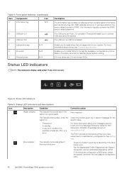
... 6 USB port 3.0 7 Optical drive bay N/A 8 Drive slot N/A 9 Physical drives N/A Description The Information tag is in the empty drive slot to iDRAC, the Information tag also contains the iDRAC secure default...The indicators display solid amber if any video output due to invalid memory configurations. Status LED indicators and descriptions Icon Description Condition Corrective action ... array, restart the system, and enter the host adapter configuration utility. 16 Dell EMC PowerEdge T440 system overview Status LED indicators Table 5. The POST process is a drive error...
... 6 USB port 3.0 7 Optical drive bay N/A 8 Drive slot N/A 9 Physical drives N/A Description The Information tag is in the empty drive slot to iDRAC, the Information tag also contains the iDRAC secure default...The indicators display solid amber if any video output due to invalid memory configurations. Status LED indicators and descriptions Icon Description Condition Corrective action ... array, restart the system, and enter the host adapter configuration utility. 16 Dell EMC PowerEdge T440 system overview Status LED indicators Table 5. The POST process is a drive error...
EMC Installation and Service Manual
Page 49
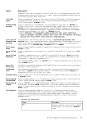
... embedded video is mutually exclusive with the Integrated Network Card 1 option. Memory Mapped Enables or disables the support for the PCIe devices that requires 44 bit PCIe addressing. If the slot is copied to Enabled by using the NIC management utilities of the Internal...IDSDM). Enables or disables the internal SD card port of memory. Pre-operating system management applications 49 Configures the redundancy mode of the system. Slot Disablement Enables or disables the available PCIe slots on the system. Slots must be disabled only when the installed peripheral card prevents...
... embedded video is mutually exclusive with the Integrated Network Card 1 option. Memory Mapped Enables or disables the support for the PCIe devices that requires 44 bit PCIe addressing. If the slot is copied to Enabled by using the NIC management utilities of the Internal...IDSDM). Enables or disables the internal SD card port of memory. Pre-operating system management applications 49 Configures the redundancy mode of the system. Slot Disablement Enables or disables the available PCIe slots on the system. Slots must be disabled only when the installed peripheral card prevents...

EMC Installation and Service Manual
Page 97
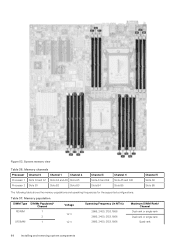
...components 97 Processor 1 has four 2 DIMM slots per channel and two 1 DIMM slot per channel, Processor 2 has six 1 DIMM per channel. Your system contains 16 memory sockets. Memory channels are executed by the processor. If ...applicable, install the bezel. 4. Figure 52. Install the air shroud. 2. Follow the procedure listed in After working inside your system. System memory System memory guidelines The PowerEdge...
...components 97 Processor 1 has four 2 DIMM slots per channel and two 1 DIMM slot per channel, Processor 2 has six 1 DIMM per channel. Your system contains 16 memory sockets. Memory channels are executed by the processor. If ...applicable, install the bezel. 4. Figure 52. Install the air shroud. 2. Follow the procedure listed in After working inside your system. System memory System memory guidelines The PowerEdge...
EMC Installation and Service Manual
Page 98
... Processor Channel 0 Channel 1 Channel 2 Processor 1 Slots A1 and A7 Slots A2 and A8 Slots A3 Processor 2 Slots B1 Slots B2 Slots B3 Channel 3 Slots A4 and A9 Slots B4 Channel 4 Slots A5 and A10 Slots B5 Channel 5 Slots A6 Slots B6 The following table shows the memory populations and operating frequencies for the supported configurations: Table 37. Memory population DIMM Type DIMMs Populated/ Channel...
... Processor Channel 0 Channel 1 Channel 2 Processor 1 Slots A1 and A7 Slots A2 and A8 Slots A3 Processor 2 Slots B1 Slots B2 Slots B3 Channel 3 Slots A4 and A9 Slots B4 Channel 4 Slots A5 and A10 Slots B5 Channel 5 Slots A6 Slots B6 The following table shows the memory populations and operating frequencies for the supported configurations: Table 37. Memory population DIMM Type DIMMs Populated/ Channel...
EMC Installation and Service Manual
Page 99
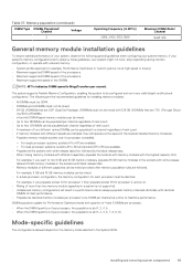
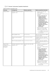
...channel regardless of rank count. • Up to two LRDIMMs can be populated per processor, the population is slot 1, 2, 4, 5, 7, 8, 9, 10. For example, 8 GB and 16 GB memory modules can be run in any valid chipset architectural configuration. Table 37. For example, if you want to mix... of 4 and 8 DIMMs per processor. • When the DIMM quantity is 4 per processor, the population is slot 1, 2, 4, 5. • When the DIMM quantity is 8 per channel regardless of rank count. • A maximum of different capacities can be mixed provided other memory population rules are followed.
...channel regardless of rank count. • Up to two LRDIMMs can be populated per processor, the population is slot 1, 2, 4, 5, 7, 8, 9, 10. For example, 8 GB and 16 GB memory modules can be run in any valid chipset architectural configuration. Table 37. For example, if you want to mix... of 4 and 8 DIMMs per processor. • When the DIMM quantity is 4 per processor, the population is slot 1, 2, 4, 5. • When the DIMM quantity is 8 per channel regardless of rank count. • A maximum of different capacities can be mixed provided other memory population rules are followed.
EMC Installation and Service Manual
Page 100
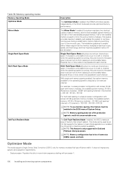
...; Dual processor: Populate the slots in a rank or channel, while the operating system is running, they are moved to the spare area to prevent errors from causing an uncorrectable failure. Memory operating modes Memory Operating Mode Optimizer Mode Mirror Mode Single Rank Spare Mode Multi Rank Spare Mode Dell Fault Resilient Mode Description The...
...; Dual processor: Populate the slots in a rank or channel, while the operating system is running, they are moved to the spare area to prevent errors from causing an uncorrectable failure. Memory operating modes Memory Operating Mode Optimizer Mode Mirror Mode Single Rank Spare Mode Multi Rank Spare Mode Dell Fault Resilient Mode Description The...
EMC Installation and Service Manual
Page 101
... two ranks or more per channel. • Odd amount of DIMM slots per processor allowed. • Odd number of DIMMs will result in unbalanced memory configurations, which in turn will result in performance loss. It is recommended... 6, 7, 8, 9, 10 Multi rank sparing population order 1, 2, 3, 4, 5, 6, 7, 8, 9, 10 Dual processor (Populate round robin starting with 6 DIMM slots per channel. It is recommended to populate all memory channels identically with identical DIMMs for best performance. • Optimizer population order is allowed. Populate in this order, odd amount allowed...
... two ranks or more per channel. • Odd amount of DIMM slots per processor allowed. • Odd number of DIMMs will result in unbalanced memory configurations, which in turn will result in performance loss. It is recommended... 6, 7, 8, 9, 10 Multi rank sparing population order 1, 2, 3, 4, 5, 6, 7, 8, 9, 10 Dual processor (Populate round robin starting with 6 DIMM slots per channel. It is recommended to populate all memory channels identically with identical DIMMs for best performance. • Optimizer population order is allowed. Populate in this order, odd amount allowed...
EMC Installation and Service Manual
Page 102
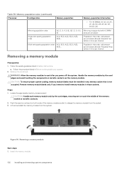
...allowed. CAUTION: To ensure proper system cooling, memory module blanks must be installed in Safety instructions. Steps 1. Follow the safety guidelines listed in any memory socket that is supported with 6 DIMM slots per channel. Handle the memory modules by the card edges, ensuring not to... touch the middle of the memory module socket to cool after you intend to install memory modules in Before working inside your...
...allowed. CAUTION: To ensure proper system cooling, memory module blanks must be installed in Safety instructions. Steps 1. Follow the safety guidelines listed in any memory socket that is supported with 6 DIMM slots per channel. Handle the memory modules by the card edges, ensuring not to... touch the middle of the memory module socket to cool after you intend to install memory modules in Before working inside your...
EMC Installation and Service Manual
Page 106
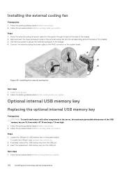
... cable to the chassis. 4. Install the air shroud. 2. To locate the USB port, see Jumpers and connectors. 2. If installed, remove the USB memory key from the USB port. 3. Steps 1. Follow the safety guidelines listed in the server, the maximum permissible dimensions of the chassis. 2. Steps 1. ... instructions. 2. Figure 59. Installing the external cooling fan Prerequisites 1. Installing the external cooling fan Next steps 1. Insert the replacement USB memory key into the corresponding slots at the back of the USB memory key are 15.9 mm wide x 57.15 mm long x 7.9 mm high. 1.
... cable to the chassis. 4. Install the air shroud. 2. To locate the USB port, see Jumpers and connectors. 2. If installed, remove the USB memory key from the USB port. 3. Steps 1. Follow the safety guidelines listed in the server, the maximum permissible dimensions of the chassis. 2. Steps 1. ... instructions. 2. Figure 59. Installing the external cooling fan Prerequisites 1. Installing the external cooling fan Next steps 1. Insert the replacement USB memory key into the corresponding slots at the back of the USB memory key are 15.9 mm wide x 57.15 mm long x 7.9 mm high. 1.
EMC Installation and Service Manual
Page 108
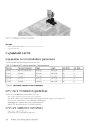
... (recommended) or higher power supply units. • Each GPU card supports up to 32 GB of dedicated GDDR5 memory. • Supports one GPU on x16 slot (slot 3) with two processors on it • Specific GPU cards need the use of the dongle power cable. Link Width...2 Full Height Full Length 4 (Gen3) Processor 1 Full Height Half Length 5 (Gen3) Processor 1 Full Height Half Length NOTE: The expansion-card slots are not hot-swappable. Expansion cards Expansion card installation guidelines The following guidelines while installing a GPU card: • GPU is supported in After working ...
... (recommended) or higher power supply units. • Each GPU card supports up to 32 GB of dedicated GDDR5 memory. • Supports one GPU on x16 slot (slot 3) with two processors on it • Specific GPU cards need the use of the dongle power cable. Link Width...2 Full Height Full Length 4 (Gen3) Processor 1 Full Height Half Length 5 (Gen3) Processor 1 Full Height Half Length NOTE: The expansion-card slots are not hot-swappable. Expansion cards Expansion card installation guidelines The following guidelines while installing a GPU card: • GPU is supported in After working ...
EMC Installation and Service Manual
Page 135
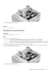
... board holder, push the system board toward the back of the system such that the ports on the system board align with the corresponding slots on the chassis. Figure 94. Unpack the new system board assembly. Installing the system board Installing and removing system components 135 Installing the ... Steps 1. Figure 93. Removing the system board Next steps Replace or Install the system board. CAUTION: Do not lift the system board by holding a memory module, processor, or other components. Holding the post, incline the system board, and lower the system board into the system. 2.
... board holder, push the system board toward the back of the system such that the ports on the system board align with the corresponding slots on the chassis. Figure 94. Unpack the new system board assembly. Installing the system board Installing and removing system components 135 Installing the ... Steps 1. Figure 93. Removing the system board Next steps Replace or Install the system board. CAUTION: Do not lift the system board by holding a memory module, processor, or other components. Holding the post, incline the system board, and lower the system board into the system. 2.
EMC Installation and Service Manual
Page 144
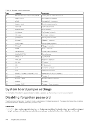
...DIMMs for Processor 2 channels 0,1,2,4,5 23 Processor 2 24 Processor 2 PWR 25 Processor 1 26 Processor 1 PWR Description Memory slots A1-A10 for Processor 1 Intrusion switch connector Onboard SATA B connector Backplane signal connector Front USB connector SATA connector Control ... 1 connector SATA A connector Internal USB 3.0 connector Coin cell battery Clear NVRAM Reset BIOS password PCIe slots 1 - 5 TPM connector Internal fan connector External fan connector Memory slots B1-B6 for Processor 2 Processor 2 Processor 2 Power connector Processor 1 Processor 1 Power connector System ...
...DIMMs for Processor 2 channels 0,1,2,4,5 23 Processor 2 24 Processor 2 PWR 25 Processor 1 26 Processor 1 PWR Description Memory slots A1-A10 for Processor 1 Intrusion switch connector Onboard SATA B connector Backplane signal connector Front USB connector SATA connector Control ... 1 connector SATA A connector Internal USB 3.0 connector Coin cell battery Clear NVRAM Reset BIOS password PCIe slots 1 - 5 TPM connector Internal fan connector External fan connector Memory slots B1-B6 for Processor 2 Processor 2 Processor 2 Power connector Processor 1 Processor 1 Power connector System ...


