Owner's Manual
Page 3
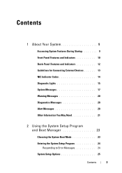
Contents 1 About Your System 9 Accessing System Features During Startup 9 Front-Panel Features and Indicators 10 Back-Panel Features and Indicators 12 Guidelines for Connecting External Devices 13 NIC Indicator Codes 14 Diagnostic Lights 15 System Messages 17 Warning Messages 20 Diagnostics Messages 20 Alert Messages 20 Other Information You May Need 21 2 Using the System Setup Program and Boot Manager 23 Choosing the System Boot Mode 23 Entering the System Setup Program 24 Responding to Error Messages 24 System Setup Options 25 Contents 3
Contents 1 About Your System 9 Accessing System Features During Startup 9 Front-Panel Features and Indicators 10 Back-Panel Features and Indicators 12 Guidelines for Connecting External Devices 13 NIC Indicator Codes 14 Diagnostic Lights 15 System Messages 17 Warning Messages 20 Diagnostics Messages 20 Alert Messages 20 Other Information You May Need 21 2 Using the System Setup Program and Boot Manager 23 Choosing the System Boot Mode 23 Entering the System Setup Program 24 Responding to Error Messages 24 System Setup Options 25 Contents 3

Owner's Manual
Page 5
... Front Bezel 47 Installing the Front Bezel 48 Removing Front-Bezel Insert 49 Installing Front-Bezel Insert 50 EMI Filler Panel 50 Removing an EMI Filler Panel 50 Installing an EMI Filler Panel 51 Optical and Tape Drives (Optional 52 Removing an Optical or Tape Drive 52 Installing an Optical or Tape Drive...
... Front Bezel 47 Installing the Front Bezel 48 Removing Front-Bezel Insert 49 Installing Front-Bezel Insert 50 EMI Filler Panel 50 Removing an EMI Filler Panel 50 Installing an EMI Filler Panel 51 Optical and Tape Drives (Optional 52 Removing an Optical or Tape Drive 52 Installing an Optical or Tape Drive...

Owner's Manual
Page 6
... Power Supply 87 Internal USB Memory Key 88 Chassis Intrusion Switch 89 Removing the Chassis Intrusion Switch 89 Installing the Chassis Intrusion Switch 90 Control Panel Assembly 91 Removing the Control Panel Assembly 91 Installing the Control...
... Power Supply 87 Internal USB Memory Key 88 Chassis Intrusion Switch 89 Removing the Chassis Intrusion Switch 89 Installing the Chassis Intrusion Switch 90 Control Panel Assembly 91 Removing the Control Panel Assembly 91 Installing the Control...

Owner's Manual
Page 10
The power button controls the DC power supply output to display an image, depending on . Front-Panel Features and Indicators 1 2 3 4 7 6 Item Indicator, Button, or Icon Connector 1 Power-on indicator, power button 5 Description The power-on indicator lights when the system power is ... installed in the system. NOTE: When powering on the system, the video monitor can take from several seconds to over 2 minutes to the system. Front-Panel Features and Indicators Figure 1-1. NOTE: On ACPI-compliant operating systems, turning off . 10 About Your System
The power button controls the DC power supply output to display an image, depending on . Front-Panel Features and Indicators 1 2 3 4 7 6 Item Indicator, Button, or Icon Connector 1 Power-on indicator, power button 5 Description The power-on indicator lights when the system power is ... installed in the system. NOTE: When powering on the system, the video monitor can take from several seconds to over 2 minutes to the system. Front-Panel Features and Indicators Figure 1-1. NOTE: On ACPI-compliant operating systems, turning off . 10 About Your System

Owner's Manual
Page 12
Back-Panel Features and Indicators 1 2 3 4 5 6 7 8 9 10 Item Indicator, Button, or Icon Connector 1 Padlock ring 2 Security cable slot 3 Power supply 4 Cable clasp Description Locks the cover release latch. Secures the power cable. 12 About Your System Connects a cable lock to the system. 305 W power supply. Back-Panel Features and Indicators Figure 1-2.
Back-Panel Features and Indicators 1 2 3 4 5 6 7 8 9 10 Item Indicator, Button, or Icon Connector 1 Padlock ring 2 Security cable slot 3 Power supply 4 Cable clasp Description Locks the cover release latch. Secures the power cable. 12 About Your System Connects a cable lock to the system. 305 W power supply. Back-Panel Features and Indicators Figure 1-2.

Owner's Manual
Page 15
... the operating system. Memory failure. See "Getting Help" on page 113. See "Troubleshooting the Processor" on page 123. See "Getting Help" on the system front panel display error codes during system startup. a non-highlighted circle indicates the light is in a normal Plug the system into a working off . Diagnostic Indicator Code Code...
... the operating system. Memory failure. See "Getting Help" on page 113. See "Troubleshooting the Processor" on page 123. See "Getting Help" on the system front panel display error codes during system startup. a non-highlighted circle indicates the light is in a normal Plug the system into a working off . Diagnostic Indicator Code Code...

Owner's Manual
Page 50
...directed by your warranty. See Figure 3-4. Installing Front-Bezel Insert CAUTION: Many repairs may only be done by a certified service technician. EMI filler panels are essential for airflow efficiency and for electromagnetic interference protection. See "Removing the Front Bezel" on the configuration of the arrow to release the shoulder... screw and pull the tab to servicing that is not authorized by Dell is not covered by the online or telephone service and support team. See Figure 3-5. 50 Installing System Components
...directed by your warranty. See Figure 3-4. Installing Front-Bezel Insert CAUTION: Many repairs may only be done by a certified service technician. EMI filler panels are essential for airflow efficiency and for electromagnetic interference protection. See "Removing the Front Bezel" on the configuration of the arrow to release the shoulder... screw and pull the tab to servicing that is not authorized by Dell is not covered by the online or telephone service and support team. See Figure 3-5. 50 Installing System Components

Owner's Manual
Page 51
...servicing that came with the product. 1 Align the screws on the EMI filler panel with the slots in your warranty. Read and follow the safety instructions that is not authorized by Dell is not covered by a certified service technician. Removing and Installing the EMI Filler... Panel 4 3 2 1 1 tab 3 shoulder screws (2) 2 EMI filler panel 4 drive release latch Installing an EMI Filler Panel CAUTION: Many repairs may only be done by ...
...servicing that came with the product. 1 Align the screws on the EMI filler panel with the slots in your warranty. Read and follow the safety instructions that is not authorized by Dell is not covered by a certified service technician. Removing and Installing the EMI Filler... Panel 4 3 2 1 1 tab 3 shoulder screws (2) 2 EMI filler panel 4 drive release latch Installing an EMI Filler Panel CAUTION: Many repairs may only be done by ...

Owner's Manual
Page 55
...screws to attach to the new drive. See "Opening the System" on page 49. 7 Remove the three shoulder screws from the EMI filler panel and attach them to servicing that accompanied the drive. 2 Turn off the system, including any attached peripherals, and disconnect the system from the ... follow the safety instructions that came with the product. 1 Unpack the drive and prepare it (see the documentation that is not authorized by Dell is not covered by your product documentation, or as directed by a certified service technician. Installing System Components 55 Damage due to the new drive...
...screws to attach to the new drive. See "Opening the System" on page 49. 7 Remove the three shoulder screws from the EMI filler panel and attach them to servicing that accompanied the drive. 2 Turn off the system, including any attached peripherals, and disconnect the system from the ... follow the safety instructions that came with the product. 1 Unpack the drive and prepare it (see the documentation that is not authorized by Dell is not covered by your product documentation, or as directed by a certified service technician. Installing System Components 55 Damage due to the new drive...

Owner's Manual
Page 86
... tabs in your warranty. See Figure 3-22. 10 Remove the cable clip and set it aside to attach to servicing that is not authorized by Dell is not covered by a certified service technician. You should only perform troubleshooting and simple repairs as authorized in the system frame as directed by the... be done by your product documentation, or as you replace them to prevent their being pinched or crimped. 6 Remove the cables secured to the back panel. 8 Press the power-supply release tab down and slide the power supply toward the front of the system. 9 Lift the power-supply out of the...
... tabs in your warranty. See Figure 3-22. 10 Remove the cable clip and set it aside to attach to servicing that is not authorized by Dell is not covered by a certified service technician. You should only perform troubleshooting and simple repairs as authorized in the system frame as directed by the... be done by your product documentation, or as you replace them to prevent their being pinched or crimped. 6 Remove the cables secured to the back panel. 8 Press the power-supply release tab down and slide the power supply toward the front of the system. 9 Lift the power-supply out of the...

Owner's Manual
Page 87
... the power supply toward the back panel until it snaps into place over the power-supply release tab. 4 Using a #2 Phillips screwdriver, install the four screws that is not authorized by Dell is not covered by your product documentation, or as authorized in your warranty. Damage due to servicing... that secure the power supply to the new power supply. 2 Align the power supply mounting holes with the product. 1 Attach the cable clip to the back panel. Figure 3-...
... the power supply toward the back panel until it snaps into place over the power-supply release tab. 4 Using a #2 Phillips screwdriver, install the four screws that is not authorized by Dell is not covered by your product documentation, or as authorized in your warranty. Damage due to servicing... that secure the power supply to the new power supply. 2 Align the power supply mounting holes with the product. 1 Attach the cable clip to the back panel. Figure 3-...

Owner's Manual
Page 88
See "Installing the Cooling Shroud" on page 65. 9 Close the system. Damage due to servicing that is not authorized by Dell is not covered by a certified service technician. See Figure 3-23. 5 Close the system. See "Installing the Expansion-Card Stabilizer" on page 67. 8 Replace the ...storage device. The USB connector must be enabled by the Internal USB Port option in the System Setup program. 88 Installing System Components 5 Secure the I/O panel and SATA cables (if present) to the routing clip on the side of the System Setup program. See "Closing the System" on the system board...
See "Installing the Cooling Shroud" on page 65. 9 Close the system. Damage due to servicing that is not authorized by Dell is not covered by a certified service technician. See Figure 3-23. 5 Close the system. See "Installing the Expansion-Card Stabilizer" on page 67. 8 Replace the ...storage device. The USB connector must be enabled by the Internal USB Port option in the System Setup program. 88 Installing System Components 5 Secure the I/O panel and SATA cables (if present) to the routing clip on the side of the System Setup program. See "Closing the System" on the system board...

Owner's Manual
Page 91
...link bracket lock out of the system. Doing so can damage the cable. 4 To disconnect the control panel cable from the electrical outlet. 2 Open the system. CAUTION: Do not pull on page 46. ... See "Removing the Front Bezel" on page 47. Damage due to unseat the connector. Removing the Control Panel Assembly 1 Turn off the system and attached peripherals, and disconnect the system from the system board, press the... follow the safety instructions that is not authorized by Dell is not covered by your product documentation, or as directed by a certified service technician.
...link bracket lock out of the system. Doing so can damage the cable. 4 To disconnect the control panel cable from the electrical outlet. 2 Open the system. CAUTION: Do not pull on page 46. ... See "Removing the Front Bezel" on page 47. Damage due to unseat the connector. Removing the Control Panel Assembly 1 Turn off the system and attached peripherals, and disconnect the system from the system board, press the... follow the safety instructions that is not authorized by Dell is not covered by your product documentation, or as directed by a certified service technician.

Owner's Manual
Page 92
... tabs on the cable to the chassis. Removing and Installing the Link Bracket Lock 1 2 1 screw 2 link bracket lock 6 Remove the mounting screw holding the control panel assembly to unseat the connector. CAUTION: Do not pull on the ends of the cable connector and gently work the connector out of the system.... Figure 3-25. See Figure 3-26. 7 Move the control panel assembly toward the back of the system and lift it out of the socket. 92 Installing System Components
... tabs on the cable to the chassis. Removing and Installing the Link Bracket Lock 1 2 1 screw 2 link bracket lock 6 Remove the mounting screw holding the control panel assembly to unseat the connector. CAUTION: Do not pull on the ends of the cable connector and gently work the connector out of the system.... Figure 3-25. See Figure 3-26. 7 Move the control panel assembly toward the back of the system and lift it out of the socket. 92 Installing System Components

Owner's Manual
Page 93
...the standoff on the side of the power supply unit. Removing and Installing the Control Panel Assembly 2 1 3 1 mounting screw 3 control-panel cable 4 2 control-panel board 4 standoff Installing the Control Panel Assembly CAUTION: Many repairs may only be done by your product documentation, or as directed...Figure 3-26. Damage due to the control panel board. 2 Align the slot in your warranty. Read and follow the safety instructions that came with the product. 1 Connect the control panel cable to servicing that is not authorized by Dell is not covered by a certified service technician...
...the standoff on the side of the power supply unit. Removing and Installing the Control Panel Assembly 2 1 3 1 mounting screw 3 control-panel cable 4 2 control-panel board 4 standoff Installing the Control Panel Assembly CAUTION: Many repairs may only be done by your product documentation, or as directed...Figure 3-26. Damage due to the control panel board. 2 Align the slot in your warranty. Read and follow the safety instructions that came with the product. 1 Connect the control panel cable to servicing that is not authorized by Dell is not covered by a certified service technician...

Owner's Manual
Page 94
... with an encryption program, you ever need to create a recovery key during operation. Read and follow the safety instructions that is not authorized by Dell is not covered by your warranty. See "Removing the Expansion-Card Stabilizer" on page 48. 7 Close the system. See "Installing the Front ...the system board, you must supply the recovery key when you restart your system or program before removing the system board. 5 Connect the control-panel cable to create and safely store this recovery key. Be sure to the system board. 6 Replace the front bezel. See "Removing an Expansion ...
... with an encryption program, you ever need to create a recovery key during operation. Read and follow the safety instructions that is not authorized by Dell is not covered by your warranty. See "Removing the Expansion-Card Stabilizer" on page 48. 7 Close the system. See "Installing the Front ...the system board, you must supply the recovery key when you restart your system or program before removing the system board. 5 Connect the control-panel cable to create and safely store this recovery key. Be sure to the system board. 6 Replace the front bezel. See "Removing an Expansion ...

Owner's Manual
Page 96
...affix them to the chassis. Read and follow the safety instructions that is not authorized by Dell is in place. 6 Tighten the ten screws to secure the system board to the system identification panel on page 71. 11 Replace the cooling fan. See Figure 3-27. 3 Holding the system... board to the new system board. See "Installing a Processor" on the system board): • SATA interface cable, if applicable • Control panel interface cable • Optical/tape drive power cable • System board power cables 10 Install all the memory modules and memory blanks. Installing the...
...affix them to the chassis. Read and follow the safety instructions that is not authorized by Dell is in place. 6 Tighten the ten screws to secure the system board to the system identification panel on page 71. 11 Replace the cooling fan. See Figure 3-27. 3 Holding the system... board to the new system board. See "Installing a Processor" on the system board): • SATA interface cable, if applicable • Control panel interface cable • Optical/tape drive power cable • System board power cables 10 Install all the memory modules and memory blanks. Installing the...
Owner's Manual
Page 99
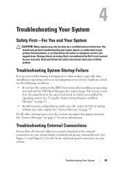
...Troubleshooting Your System 99 Damage due to servicing that came with the product. Read and follow the safety instructions that is not authorized by Dell is also true. Troubleshooting External Connections Ensure that appear onscreen. See Figure 1-1 and Figure 1-2 for more information. See "Using the ...Troubleshooting System Startup Failure If your system halts during startup prior to the external connectors on page 17 for the front- and back-panel connectors on page 73. 4 Troubleshooting Your System Safety First-For You and Your System CAUTION: Many repairs may only be done ...
...Troubleshooting Your System 99 Damage due to servicing that came with the product. Read and follow the safety instructions that is not authorized by Dell is also true. Troubleshooting External Connections Ensure that appear onscreen. See Figure 1-1 and Figure 1-2 for more information. See "Using the ...Troubleshooting System Startup Failure If your system halts during startup prior to the external connectors on page 17 for the front- and back-panel connectors on page 73. 4 Troubleshooting Your System Safety First-For You and Your System CAUTION: Many repairs may only be done ...

Owner's Manual
Page 105
...the online or telephone service and support team. Ensure that none of the following conditions exist: • System cover, cooling shroud, EMI filler panel, memory-module blank, or back-filler bracket is removed. • Ambient temperature is too high. • External airflow is obstructed. •...; The cooling fan is working properly. Damage due to servicing that is not authorized by Dell is not covered by your warranty. Troubleshooting Power Supply CAUTION: Many repairs may only be done by removing and reinstalling it is removed...
...the online or telephone service and support team. Ensure that none of the following conditions exist: • System cover, cooling shroud, EMI filler panel, memory-module blank, or back-filler bracket is removed. • Ambient temperature is too high. • External airflow is obstructed. •...; The cooling fan is working properly. Damage due to servicing that is not authorized by Dell is not covered by your warranty. Troubleshooting Power Supply CAUTION: Many repairs may only be done by removing and reinstalling it is removed...

Owner's Manual
Page 121
... Internal USB key 1 and 2 Processor DIMM_A2 memory module slot DIMM_A1 memory module slot Power connector 12 V DIMM_B1 memory module slot DIMM_B2 memory module slot Control panel connector SATA connector SATA connector SATA connector SATA connector Power connector Intrusion switch connector SATA connector Jumpers and Connectors 121
... Internal USB key 1 and 2 Processor DIMM_A2 memory module slot DIMM_A1 memory module slot Power connector 12 V DIMM_B1 memory module slot DIMM_B2 memory module slot Control panel connector SATA connector SATA connector SATA connector SATA connector Power connector Intrusion switch connector SATA connector Jumpers and Connectors 121


