
Information Update
Page 1
... sink fins to prevent damage to train: DIMM x Causes Faulty or improperly installed memory module. Reseat memory modules. If the problem persists, see "Troubleshooting System Memory" in your Hardware Owner's Manual. See "Memory" in your Dell sales agent to ensure compatibility. Dell™ PowerEdge™ SC 1430 Systems Information Update Installing a Fourth Hard Drive A fourth hard drive...
... sink fins to prevent damage to train: DIMM x Causes Faulty or improperly installed memory module. Reseat memory modules. If the problem persists, see "Troubleshooting System Memory" in your Hardware Owner's Manual. See "Memory" in your Dell sales agent to ensure compatibility. Dell™ PowerEdge™ SC 1430 Systems Information Update Installing a Fourth Hard Drive A fourth hard drive...

Getting Started Guide
Page 5
...wired for the following resolutions: 640 x 480, 800 x 600, 1024 x 768, 1280 x 1024 Getting Started With Your System 3 The upgrade kit from Dell. A controller expansion card is required for SAS hard drives or for more than two SATA hard drives. • One 3.5-inch flex bay for a diskette... device (second bay only), or fourth hard drive (second bay only, hard drive carrier required) NOTE: DVD devices are supported in the four memory module sockets on systems with support for USB 2.0 • Chassis intrusion alert The system board includes the following built-in the flex bay. NOTE...
...wired for the following resolutions: 640 x 480, 800 x 600, 1024 x 768, 1280 x 1024 Getting Started With Your System 3 The upgrade kit from Dell. A controller expansion card is required for SAS hard drives or for more than two SATA hard drives. • One 3.5-inch flex bay for a diskette... device (second bay only), or fourth hard drive (second bay only, hard drive carrier required) NOTE: DVD devices are supported in the four memory module sockets on systems with support for USB 2.0 • Chassis intrusion alert The system board includes the following built-in the flex bay. NOTE...
Getting Started Guide
Page 6
...LAN • Seven USB 2.0-compliant connectors (two on the front and five on page 7. NOTE: Always check for updates on support.dell.com and read the updates first because they often supersede information in other documents. • Release notes or readme files may be ...• Microsoft Windows® Small Business Server 2003 Standard and Premium Editions • Red Hat® Enterprise Linux (version 4) for Intel Extended Memory 64 Technology (Intel EM64T) • SUSE® LINUX Enterprise Server 9 Other Information You May Need CAUTION: The Product Information Guide provides important ...
...LAN • Seven USB 2.0-compliant connectors (two on the front and five on page 7. NOTE: Always check for updates on support.dell.com and read the updates first because they often supersede information in other documents. • Release notes or readme files may be ...• Microsoft Windows® Small Business Server 2003 Standard and Premium Editions • Red Hat® Enterprise Linux (version 4) for Intel Extended Memory 64 Technology (Intel EM64T) • SUSE® LINUX Enterprise Server 9 Other Information You May Need CAUTION: The Product Information Guide provides important ...

Getting Started Guide
Page 10
Technical Specifications Processor Processor type Expansion Bus Bus type Expansion slots PCIe PCI-X PCI Memory Architecture Memory module sockets Memory module capacities Minimum RAM Maximum RAM one or two Dual-Core Intel Xeon Processors 5000 Sequence PCIe, PCI-X, PCI one half-length, full-height, x4 ...
Technical Specifications Processor Processor type Expansion Bus Bus type Expansion slots PCIe PCI-X PCI Memory Architecture Memory module sockets Memory module capacities Minimum RAM Maximum RAM one or two Dual-Core Intel Xeon Processors 5000 Sequence PCIe, PCI-X, PCI one half-length, full-height, x4 ...
Getting Started Guide
Page 12
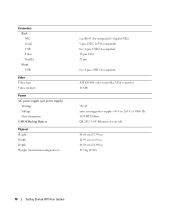
Connectors Back NIC Serial USB Video Parallel Front USB Video Video type Video memory Power AC power supply (per power supply) Wattage Voltage Heat dissipation CMOS Backup Battery Physical Height Width Depth Weight (maximum configuration) one RJ-45 (for ...
Connectors Back NIC Serial USB Video Parallel Front USB Video Video type Video memory Power AC power supply (per power supply) Wattage Voltage Heat dissipation CMOS Backup Battery Physical Height Width Depth Weight (maximum configuration) one RJ-45 (for ...

Hardware Owner's Manual
Page 5
Memory 76 General Memory Module Installation Guidelines 77 Non-Optimal Memory Configurations 77 Installing Memory Modules 77 Removing Memory Modules 79 System Battery 79 Replacing the System Battery 79 Power Supply 81 Removing the Power Supply 81 Installing the Power Supply 82 ...Replacing the Cooling Fans 83 Replacing the Card and Front Fans 83 Replacing the Memory Fan 85 Replacing the Fourth Hard-Drive Fan 86 Chassis Intrusion Switch 86 Removing the Chassis Intrusion Switch 86 Installing the Chassis Intrusion Switch...
Memory 76 General Memory Module Installation Guidelines 77 Non-Optimal Memory Configurations 77 Installing Memory Modules 77 Removing Memory Modules 79 System Battery 79 Replacing the System Battery 79 Power Supply 81 Removing the Power Supply 81 Installing the Power Supply 82 ...Replacing the Cooling Fans 83 Replacing the Card and Front Fans 83 Replacing the Memory Fan 85 Replacing the Fourth Hard-Drive Fan 86 Chassis Intrusion Switch 86 Removing the Chassis Intrusion Switch 86 Installing the Chassis Intrusion Switch...

Hardware Owner's Manual
Page 6
... Cooling Problems 102 Troubleshooting a Fan 103 Troubleshooting System Memory 103 Troubleshooting a Diskette Drive 105 Troubleshooting an Optical Drive 106 Troubleshooting a Hard Drive 107 Troubleshooting a SAS RAID Controller 108 Troubleshooting Expansion Cards 109 Troubleshooting the Microprocessors 110 5 Running the System Diagnostics 113 Using Dell PowerEdge Diagnostics 113 System Diagnostics Features 113 When to Use...
... Cooling Problems 102 Troubleshooting a Fan 103 Troubleshooting System Memory 103 Troubleshooting a Diskette Drive 105 Troubleshooting an Optical Drive 106 Troubleshooting a Hard Drive 107 Troubleshooting a SAS RAID Controller 108 Troubleshooting Expansion Cards 109 Troubleshooting the Microprocessors 110 5 Running the System Diagnostics 113 Using Dell PowerEdge Diagnostics 113 System Diagnostics Features 113 When to Use...

Hardware Owner's Manual
Page 16
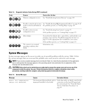
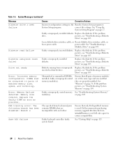
...Getting Help" on page 109. mode. Possible processor failure. See "Troubleshooting System Memory" on page 123. See "Getting Help" on page 103. See "Troubleshooting a USB Device" on page 95. No memory modules detected. See "Troubleshooting Your System" on page 99. If the problem .... See "Hard Drives" on page 48 and "Diskette Drive" on page 63 for information on page 123. See "Troubleshooting System Memory" on page 103. Possible USB failure. Table 1-4. Diagnostic Indicator Codes Before POST (continued) Code Power Light off Causes Corrective Action ...
...Getting Help" on page 109. mode. Possible processor failure. See "Troubleshooting System Memory" on page 123. See "Getting Help" on page 103. See "Troubleshooting a USB Device" on page 95. No memory modules detected. See "Troubleshooting Your System" on page 99. If the problem .... See "Hard Drives" on page 48 and "Diskette Drive" on page 63 for information on page 123. See "Troubleshooting System Memory" on page 103. Possible USB failure. Table 1-4. Diagnostic Indicator Codes Before POST (continued) Code Power Light off Causes Corrective Action ...
Hardware Owner's Manual
Page 17
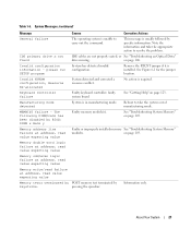
Table 1-5. Diagnostic Indicator Codes During POST (continued) Code Causes Memory configuration error. The system is in your Product Information Guide for the appropriate drive installed in a normal operating condition after POST. System Messages ...action. failure. If the problem persists, see "Getting Help" on page 89. Table 1-6. About Your System 17 Other failure. Corrective Action See "Troubleshooting System Memory" on page 95. Table 1-6 lists the system messages that is not listed in the improperly installed or has failed. If and/or system board hardware...
Table 1-5. Diagnostic Indicator Codes During POST (continued) Code Causes Memory configuration error. The system is in your Product Information Guide for the appropriate drive installed in a normal operating condition after POST. System Messages ...action. failure. If the problem persists, see "Getting Help" on page 89. Table 1-6. About Your System 17 Other failure. Corrective Action See "Troubleshooting System Memory" on page 95. Table 1-6 lists the system messages that is not listed in the improperly installed or has failed. If and/or system board hardware...

Hardware Owner's Manual
Page 18
...the INTRUDER connector on page 102. FAN_CCAG was not detected. FAN_MEM was not detected. Previous FAN_MEM failure. card fan • FAN_FRONT - memory fan Corrective Actions Verify that the chassis intrusion switch cable is applied to the system board. Information only. card fan • FAN_FRONT ...cover has been opened. front fan • FAN_HDD - Alert! FAN_HDD was not detected. Alert! See "Getting Help" on page 87. memory fan • FAN_PSU - the heat sink and the heat sink is not connected to the last system startup. Cover was not detected. Previous...
...the INTRUDER connector on page 102. FAN_CCAG was not detected. FAN_MEM was not detected. Previous FAN_MEM failure. card fan • FAN_FRONT - memory fan Corrective Actions Verify that the chassis intrusion switch cable is applied to the system board. Information only. card fan • FAN_FRONT ...cover has been opened. front fan • FAN_HDD - Alert! FAN_HDD was not detected. Alert! See "Getting Help" on page 87. memory fan • FAN_PSU - the heat sink and the heat sink is not connected to the last system startup. Cover was not detected. Previous...

Hardware Owner's Manual
Page 19
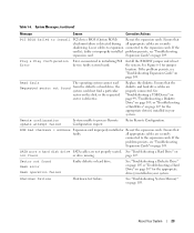
... mode with slot 1. The system will operate in size, speed, and technology. If the problem persists, see "Troubleshooting System Memory" on page 103. Dual-rank DIMM paired with different cache sizes are properly installed. If the problem rank of the same ... with different cache sizes detected! on must be populated in pairs. CPUs with a single-rank DIMM. Decreasing available memory Faulty or improperly installed memory See "Troubleshooting System Memory" modules. The following DIMM pair is mismatched: DIMM x and DIMM y. The following DIMM/rank has been disabled...
... mode with slot 1. The system will operate in size, speed, and technology. If the problem persists, see "Troubleshooting System Memory" on page 103. Dual-rank DIMM paired with different cache sizes are properly installed. If the problem rank of the same ... with different cache sizes detected! on must be populated in pairs. CPUs with a single-rank DIMM. Decreasing available memory Faulty or improperly installed memory See "Troubleshooting System Memory" modules. The following DIMM pair is mismatched: DIMM x and DIMM y. The following DIMM/rank has been disabled...
Hardware Owner's Manual
Page 20
... "Troubleshooting a Diskette Drive" on page 105. Ensure that are properly installed. Faulty or improperly installed diskette Replace the diskette. faulty or improperly seated memory module(s). Dell recommends purchasing memory upgrade kits directly from or improperly Replace the diskette. Replace the faulty DIMM as soon as possible. on page 103. System Messages (continued) Message...
... "Troubleshooting a Diskette Drive" on page 105. Ensure that are properly installed. Faulty or improperly installed diskette Replace the diskette. faulty or improperly seated memory module(s). Dell recommends purchasing memory upgrade kits directly from or improperly Replace the diskette. Replace the faulty DIMM as soon as possible. on page 103. System Messages (continued) Message...
Hardware Owner's Manual
Page 21
... is in manufacturing mode. Faulty keyboard controller; faulty system board System is installed. Reboot to resolve the problem. Information only. Faulty or improperly installed memory See "Troubleshooting System Memory" modules. About Your System 21 Table 1-6. please run SETUP program Invalid NVRAM configuration, Resource Re-allocated Keyboard Controller failure Manufacturing mode detected MEMBIST...
... is in manufacturing mode. Faulty keyboard controller; faulty system board System is installed. Reboot to resolve the problem. Information only. Faulty or improperly installed memory See "Troubleshooting System Memory" modules. About Your System 21 Table 1-6. please run SETUP program Invalid NVRAM configuration, Resource Re-allocated Keyboard Controller failure Manufacturing mode detected MEMBIST...

Hardware Owner's Manual
Page 22
The specified DIMM was unable to establish a successful data link with the memory controller. See your hard drive. Reseat the PCIe card in the specified slot number. See "Expansion Cards" on page 27 for information about setting the ... card in the System Setup program. If the problem persists, see "Getting Help" on hard drive. Reseat the PCIe card in drive A. See "Troubleshooting System Memory" on page 70. See "Expansion Cards" on page 103. System Messages (continued) Message No boot device available No boot sector on hard drive No timer...
The specified DIMM was unable to establish a successful data link with the memory controller. See your hard drive. Reseat the PCIe card in the specified slot number. See "Expansion Cards" on page 27 for information about setting the ... card in the System Setup program. If the problem persists, see "Getting Help" on hard drive. Reseat the PCIe card in drive A. See "Troubleshooting System Memory" on page 70. See "Expansion Cards" on page 103. System Messages (continued) Message No boot device available No boot sector on hard drive No timer...
Hardware Owner's Manual
Page 23
..." on page 107 for the appropriate drive(s) installed in your system. If the problem persists, see "Troubleshooting Expansion Cards" on page 109. See "Troubleshooting System Memory" on page 107 for jumper location. See "Troubleshooting a USB Device" on page 99, "Troubleshooting a Diskette Drive" on page 105, or "Troubleshooting a Hard Drive" on page...
..." on page 107 for the appropriate drive(s) installed in your system. If the problem persists, see "Troubleshooting Expansion Cards" on page 109. See "Troubleshooting System Memory" on page 107 for jumper location. See "Troubleshooting a USB Device" on page 99, "Troubleshooting a Diskette Drive" on page 105, or "Troubleshooting a Hard Drive" on page...

Hardware Owner's Manual
Page 24
... faulty chip. See system battery. Update the BIOS firmware. See "Getting Help" on the boot hard drive. Dell recommends purchasing memory upgrade kits directly from www.dell.com or your Dell sales agent to determine if single-bit or multi-bit errors were detected and replace the faulty... memory module. Dell recommends purchasing memory upgrade kits directly from www.dell.com or your Dell sales agent to ensure compatibility. faulty Check the Time and Date settings. See "Getting Help" on page 73....
... faulty chip. See system battery. Update the BIOS firmware. See "Getting Help" on the boot hard drive. Dell recommends purchasing memory upgrade kits directly from www.dell.com or your Dell sales agent to determine if single-bit or multi-bit errors were detected and replace the faulty... memory module. Dell recommends purchasing memory upgrade kits directly from www.dell.com or your Dell sales agent to ensure compatibility. faulty Check the Time and Date settings. See "Getting Help" on page 73....

Hardware Owner's Manual
Page 25
... copy of 2 or 4 DIMMs. DIMMs should be populated sequentially starting in this section. Dell recommends a population of the Diagnostics Checklist in this table, see the systems management software documentation. See "Memory" on page 149. Diagnostic error messages are generated by typing y (yes) or n ... respond before you format a diskette, a message will run system diagnostics, an error message may lose all memory accessible but nonoptimal population of an abbreviation or acronym used in slot 1. System Messages (continued) Message Causes Corrective Actions Warning: The ...
... copy of 2 or 4 DIMMs. DIMMs should be populated sequentially starting in this section. Dell recommends a population of the Diagnostics Checklist in this table, see the systems management software documentation. See "Memory" on page 149. Diagnostic error messages are generated by typing y (yes) or n ... respond before you format a diskette, a message will run system diagnostics, an error message may lose all memory accessible but nonoptimal population of an abbreviation or acronym used in slot 1. System Messages (continued) Message Causes Corrective Actions Warning: The ...
Hardware Owner's Manual
Page 27
... your operating system begins to load before you press , allow the system to familiarize yourself with your system configuration and optional settings. NOTE: After installing a memory upgrade, it is booting, make a note of the message and suggestions for correcting errors. Using the System Setup Program 27 If an error message appears...
... your operating system begins to load before you press , allow the system to familiarize yourself with your system configuration and optional settings. NOTE: After installing a memory upgrade, it is booting, make a note of the message and suggestions for correcting errors. Using the System Setup Program 27 If an error message appears...
Hardware Owner's Manual
Page 29
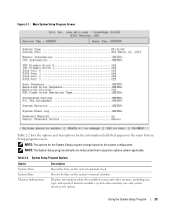
... on the system's internal clock. Using the System Setup Program 29 Displays information related to installed system and video memory, including size, type, and speed of memory modules, system video memory size and system memory test option. NOTE: The options for the information fields that appear on the system configuration. Main System Setup Program...
... on the system's internal clock. Using the System Setup Program 29 Displays information related to installed system and video memory, including size, type, and speed of memory modules, system video memory size and system memory test option. NOTE: The options for the information fields that appear on the system configuration. Main System Setup Program...

Hardware Owner's Manual
Page 31
... disables the hardware prefetcher. CPU Information Screens Table 2-3 lists the options and descriptions for applications that require high use of random memory access. Bus Speed Displays the bus speed of sequential memory access. when disabled, the CPU Performance State tables will not be used by the operating system. Using the System Setup...
... disables the hardware prefetcher. CPU Information Screens Table 2-3 lists the options and descriptions for applications that require high use of random memory access. Bus Speed Displays the bus speed of sequential memory access. when disabled, the CPU Performance State tables will not be used by the operating system. Using the System Setup...


