Information Update - Intel Xeon 5600 Series Processors
Page 2
... BIOS configuration of both standard and low voltage memory modules For information on the memory configuration guidelines, see your system's Hardware Owner's Manual at standard voltage (1.5 V) without any of the following conditions exist: • Intel Xeon 5500 series processors • Two 1333 MHz...-compatible to Intel Xeon 5500 series and operates at support.dell.com/manuals. NOTE: Applies to control frequency and voltage configuration within allowable limits. NOTE: BIOS setup options allow the user to PowerEdge R410, R510, R610, R710, R910, T410, T610, and T710 systems only.
... BIOS configuration of both standard and low voltage memory modules For information on the memory configuration guidelines, see your system's Hardware Owner's Manual at standard voltage (1.5 V) without any of the following conditions exist: • Intel Xeon 5500 series processors • Two 1333 MHz...-compatible to Intel Xeon 5500 series and operates at support.dell.com/manuals. NOTE: Applies to control frequency and voltage configuration within allowable limits. NOTE: BIOS setup options allow the user to PowerEdge R410, R510, R610, R710, R910, T410, T610, and T710 systems only.
Information Update
Page 5
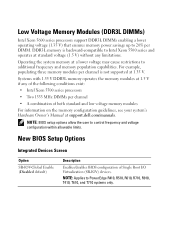
...system does not complete POST if 64 KB I/O address space is exceeded. For more than 4 KB of I/O address space. Dell Update Package Information During the Dell Update Package (DUP) installation process, you may reboot in the middle of 4 KB set too short) NIC Teaming The system...the slots with other vendors such as Intel. Due to 10. Information Update 5 The system may see the Dell™ PowerEdge™ R910 Hardware Owner's Manual at support.dell.com/manuals. It is recommended that you use Broadcom teaming driver. System Limitations With an Optional PCIe Riser The PCIe ...
...system does not complete POST if 64 KB I/O address space is exceeded. For more than 4 KB of I/O address space. Dell Update Package Information During the Dell Update Package (DUP) installation process, you may reboot in the middle of 4 KB set too short) NIC Teaming The system...the slots with other vendors such as Intel. Due to 10. Information Update 5 The system may see the Dell™ PowerEdge™ R910 Hardware Owner's Manual at support.dell.com/manuals. It is recommended that you use Broadcom teaming driver. System Limitations With an Optional PCIe Riser The PCIe ...
Information Update
Page 6
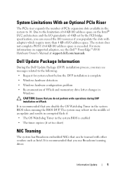
Dell Lifecycle Controller System Services Limitations Table 1. booting to two PERC H800 adapters. Under the same condition, if you enable Collect System Inventory on Restart (CSIOR), ... embedded system diagnostics without an H800 adapter installed in an inactive or non-optimal state. For more information, see the iDRAC User's Guide at support.dell.com/manuals. Dell PERC H800 Storage Adapter Slot Limitation (With PERC H700i as the Internal Storage Controller) The system supports up .
Dell Lifecycle Controller System Services Limitations Table 1. booting to two PERC H800 adapters. Under the same condition, if you enable Collect System Inventory on Restart (CSIOR), ... embedded system diagnostics without an H800 adapter installed in an inactive or non-optimal state. For more information, see the iDRAC User's Guide at support.dell.com/manuals. Dell PERC H800 Storage Adapter Slot Limitation (With PERC H700i as the Internal Storage Controller) The system supports up .
Information Update
Page 7
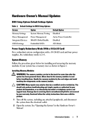
.... Allow time for installing and removing the memory modules if your system has a memory riser as shown in Figure 1. Hardware Owner's Manual Updates BIOS Setup Options Default Settings Update Table 2. Installing Memory Modules WARNING: The memory modules are hot to servicing that came with a...disconnect the system from the electrical outlet. 2 Open the system. Read and follow the safety instructions that is not authorized by Dell is 2+1. Information Update 7 Default Settings for some time after the system has been powered down. You should only perform troubleshooting...
.... Allow time for installing and removing the memory modules if your system has a memory riser as shown in Figure 1. Hardware Owner's Manual Updates BIOS Setup Options Default Settings Update Table 2. Installing Memory Modules WARNING: The memory modules are hot to servicing that came with a...disconnect the system from the electrical outlet. 2 Open the system. Read and follow the safety instructions that is not authorized by Dell is 2+1. Information Update 7 Default Settings for some time after the system has been powered down. You should only perform troubleshooting...
Information Update
Page 8
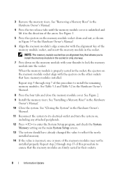
...firmly seated in the direction of the arrow. See Figure 2. 9 Install the memory risers. See "Closing the System" in the Hardware Owner's Manual. 11 Reconnect the system to its electrical outlet and turn the system on, including any attached peripherals. 12 Press to reflect the newly installed memory.... 14 If the value is unlatched and lift it in their sockets. 8 Information Update See "Removing a Memory Riser" in the Hardware Owner's Manual. 4 Press the two release tabs until the memory module cover is incorrect, one way. 7 Press down and out, as shown in Figure 3-9 in...
...firmly seated in the direction of the arrow. See Figure 2. 9 Install the memory risers. See "Closing the System" in the Hardware Owner's Manual. 11 Reconnect the system to its electrical outlet and turn the system on, including any attached peripherals. 12 Press to reflect the newly installed memory.... 14 If the value is unlatched and lift it in their sockets. 8 Information Update See "Removing a Memory Riser" in the Hardware Owner's Manual. 4 Press the two release tabs until the memory module cover is incorrect, one way. 7 Press down and out, as shown in Figure 3-9 in...

Information Update
Page 9
Figure 1. 15 Run the system memory test in the Hardware Owner's Manual. See "Running the Embedded System Diagnostics" in the system diagnostics. Installing and Removing a Memory Module 2 3 1 4 6 1 release tabs (2) 3 memory riser 5 card guide 5 2 handle 4 release button 6 memory-riser connector Information Update 9
Figure 1. 15 Run the system memory test in the Hardware Owner's Manual. See "Running the Embedded System Diagnostics" in the system diagnostics. Installing and Removing a Memory Module 2 3 1 4 6 1 release tabs (2) 3 memory riser 5 card guide 5 2 handle 4 release button 6 memory-riser connector Information Update 9
Information Update
Page 10
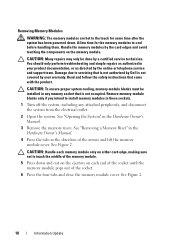
...system has been powered down and out on the ejectors on the memory module. Damage due to servicing that is not authorized by Dell is not occupied. CAUTION: To ensure proper system cooling, memory-module blanks must be done by the online or telephone service and .... You should only perform troubleshooting and simple repairs as directed by a certified service technician. See "Removing a Memory Riser" in the Hardware Owner's Manual. 4 Press the tabs in your warranty. Removing Memory Modules WARNING: The memory modules are hot to the touch for the memory modules to cool ...
...system has been powered down and out on the ejectors on the memory module. Damage due to servicing that is not authorized by Dell is not occupied. CAUTION: To ensure proper system cooling, memory-module blanks must be done by the online or telephone service and .... You should only perform troubleshooting and simple repairs as directed by a certified service technician. See "Removing a Memory Riser" in the Hardware Owner's Manual. 4 Press the tabs in your warranty. Removing Memory Modules WARNING: The memory modules are hot to the touch for the memory modules to cool ...
Information Update
Page 11
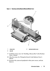
See "Closing the System" in the Hardware Owner's Manual. 8 Close the system. See "Installing a Memory Riser" in the Hardware Owner's Manual. 9 Reconnect the system and peripherals to their power sources, and turn them on. Removing and Installing the Memory Module Cover 1 3 2 1 release tab 3 tabs (4) 2 memory module cover 7 Install the memory risers. Information Update 11 Figure 2.
See "Closing the System" in the Hardware Owner's Manual. 8 Close the system. See "Installing a Memory Riser" in the Hardware Owner's Manual. 9 Reconnect the system and peripherals to their power sources, and turn them on. Removing and Installing the Memory Module Cover 1 3 2 1 release tab 3 tabs (4) 2 memory module cover 7 Install the memory risers. Information Update 11 Figure 2.
Information Update
Page 17
PCIe PCIe PCIe 10 Intel® IA32 64 KB I/O PCI 4 KB I/O 4 KB I/O I/O 64 KB I/O POST support.dell.com/manuals 上的 Dell™ PowerEdge™ R910 Hardware Owner's Manual(Dell™ PowerEdge™ R910 Dell Update Package 信息 在安装 Dell Update Package (DUP • Request for system reboot before the DUP installation is complete (在 DUP •...
PCIe PCIe PCIe 10 Intel® IA32 64 KB I/O PCI 4 KB I/O 4 KB I/O I/O 64 KB I/O POST support.dell.com/manuals 上的 Dell™ PowerEdge™ R910 Hardware Owner's Manual(Dell™ PowerEdge™ R910 Dell Update Package 信息 在安装 Dell Update Package (DUP • Request for system reboot before the DUP installation is complete (在 DUP •...
Getting Started Guide
Page 9
...; 6.0 (when available) • VMware® ESX Version 4.0 Update 1 (when available) • VMware ESXi Version 4.0 Update 1 NOTE: For the latest information on support.dell.com/manuals and read the updates first because they often supersede information in other documents. This document is available online at support....dell.com/manuals. • Any media that ships with your system that shipped with your system. Other Information You May Need WARNING: See the ...
...; 6.0 (when available) • VMware® ESX Version 4.0 Update 1 (when available) • VMware ESXi Version 4.0 Update 1 NOTE: For the latest information on support.dell.com/manuals and read the updates first because they often supersede information in other documents. This document is available online at support....dell.com/manuals. • Any media that ships with your system that shipped with your system. Other Information You May Need WARNING: See the ...
Getting Started Guide
Page 10
...guide or if the system does not perform as expected, see your Hardware Owner's Manual. Obtaining Technical Assistance If you do not understand a procedure in all locations. See www.dell.com/training for more information. Technical Specifications Processor Processor type Two or four Intel...® Xeon® 7500 series processors (up to four additional PCIe x4 Gen2 low profile slots using an optional PCIe expansion riser. Dell™ offers comprehensive...
...guide or if the system does not perform as expected, see your Hardware Owner's Manual. Obtaining Technical Assistance If you do not understand a procedure in all locations. See www.dell.com/training for more information. Technical Specifications Processor Processor type Two or four Intel...® Xeon® 7500 series processors (up to four additional PCIe x4 Gen2 low profile slots using an optional PCIe expansion riser. Dell™ offers comprehensive...
Hardware Owner's Manual
Page 1
Dell™ PowerEdge™ R910 Hardware Owner's Manual Regulatory Model: E06S Series Regulatory Type: E06S001
Dell™ PowerEdge™ R910 Hardware Owner's Manual Regulatory Model: E06S Series Regulatory Type: E06S001
Hardware Owner's Manual
Page 41
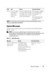
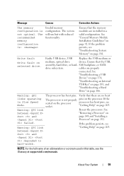
... the system is not Wait for an explanation of a possible problem with the system. Rebooting. If the problem persists, see the Glossary at support.dell.com/manuals. iDRAC6 not The iDRAC6 is page 179. Check PSU cables. System Messages Message Causes Corrective Actions Alert! Code Text Causes Corrective Actions W1630 Power supply...
... the system is not Wait for an explanation of a possible problem with the system. Rebooting. If the problem persists, see the Glossary at support.dell.com/manuals. iDRAC6 not The iDRAC6 is page 179. Check PSU cables. System Messages Message Causes Corrective Actions Alert! Code Text Causes Corrective Actions W1630 Power supply...
Hardware Owner's Manual
Page 59
See "General Memory Module Installation Guidelines" on page 186. See "Troubleshooting a USB Device" on page 174, "Troubleshooting an Internal USB Key" on page 183, and "Troubleshooting a Hard Drive" on page 92. "Getting Help" on Port and page 148 and "Installing a Warning: QPI link Reseat the processors. See between "Removing a Processor" on page 203. cables are installed in Slow Speed Mode. Faulty USB device, USB Replace the USB medium or medium, optical drive device. If the seated on the processor. Ensure that the memory modules are properly connected....
See "General Memory Module Installation Guidelines" on page 186. See "Troubleshooting a USB Device" on page 174, "Troubleshooting an Internal USB Key" on page 183, and "Troubleshooting a Hard Drive" on page 92. "Getting Help" on Port and page 148 and "Installing a Warning: QPI link Reseat the processors. See between "Removing a Processor" on page 203. cables are installed in Slow Speed Mode. Faulty USB device, USB Replace the USB medium or medium, optical drive device. If the seated on the processor. Ensure that the memory modules are properly connected....
Hardware Owner's Manual
Page 61
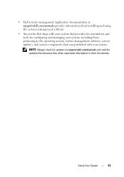
NOTE: Always check for configuring and managing your system. • Dell systems management application documentation at support.dell.com/manuals provides information about installing and using the systems management software. • Any media that ships with your system that you purchased with ... pertaining to the operating system, system management software, system updates, and system components that provides documentation and tools for updates on support.dell.com/manuals and read the updates first because they often supersede information in other documents. About Your System 61
NOTE: Always check for configuring and managing your system. • Dell systems management application documentation at support.dell.com/manuals provides information about installing and using the systems management software. • Any media that ships with your system that you purchased with ... pertaining to the operating system, system management software, system updates, and system components that provides documentation and tools for updates on support.dell.com/manuals and read the updates first because they often supersede information in other documents. About Your System 61
Hardware Owner's Manual
Page 70
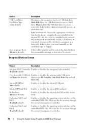
... Port (On default) Enables or disables the internal USB port. Floppy allows the USB flash drive to act as a removable diskette drive. If you must manually set the emulation type to boot, the system will automatically emulate a hard drive. The NICs can also be accessed through the system's management controller. 70...
... Port (On default) Enables or disables the internal USB port. Floppy allows the USB flash drive to act as a removable diskette drive. If you must manually set the emulation type to boot, the system will automatically emulate a hard drive. The NICs can also be accessed through the system's management controller. 70...
Hardware Owner's Manual
Page 71
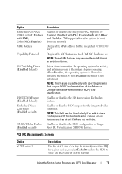
... the integrated NIC. If this field is usable only with iSCSI Boot, and Disabled. PCI IRQ Assignments Screen Option Description Use the and keys to manually select an IRQ for a given device, or select Default to allow the BIOS to monitor the operating system for activity, and aids in video card...
... the integrated NIC. If this field is usable only with iSCSI Boot, and Disabled. PCI IRQ Assignments Screen Option Description Use the and keys to manually select an IRQ for a given device, or select Default to allow the BIOS to monitor the operating system for activity, and aids in video card...
Hardware Owner's Manual
Page 82
..., perform the steps in three attempts, the system lets you do not enter the correct password in "Assigning a Setup Password" on the Dell Support website at support.dell.com/manuals. 82 Using the System Setup Program and UEFI Boot Manager Operating With a Setup Password Enabled If Setup Password is Enabled, you can assign...
..., perform the steps in three attempts, the system lets you do not enter the correct password in "Assigning a Setup Password" on the Dell Support website at support.dell.com/manuals. 82 Using the System Setup Program and UEFI Boot Manager Operating With a Setup Password Enabled If Setup Password is Enabled, you can assign...

