
Owner's Manual
Page 9
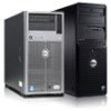
... is turned off . Allows you to insert USB devices to toggle the system ID on the back flashes blue until one of a paper clip. The ports are USB 2.0-compliant.
... is turned off . Allows you to insert USB devices to toggle the system ID on the back flashes blue until one of a paper clip. The ports are USB 2.0-compliant.

Owner's Manual
Page 11
... system is turned off through the iDRAC utility, the LCD panel, or other tools. 11 LCD Panel Features NOTE: The LCD panel is off . The port is operating correctly or when the system needs attention. To reset the iDRAC (if not disabled in F2 iDRAC setup) press and hold the system...
... system is turned off through the iDRAC utility, the LCD panel, or other tools. 11 LCD Panel Features NOTE: The LCD panel is off . The port is operating correctly or when the system needs attention. To reset the iDRAC (if not disabled in F2 iDRAC setup) press and hold the system...
Owner's Manual
Page 15
... expansion card slot (riser 2) Allows you to connect the optional system status indicator assembly through the optional cable management arm. 3 iDRAC7 Enterprise port Dedicated management port. To reset iDRAC (if not disabled in F2 iDRAC setup) press and hold the system ID button for more than five seconds to toggle...the system status indicator on and off until one of the buttons is pressed again. Press to enter BIOS progress mode. NOTE: The port is available for use only if the iDRAC7 Enterprise license is installed on the front and back panels can be used to connect a ...
... expansion card slot (riser 2) Allows you to connect the optional system status indicator assembly through the optional cable management arm. 3 iDRAC7 Enterprise port Dedicated management port. To reset iDRAC (if not disabled in F2 iDRAC setup) press and hold the system ID button for more than five seconds to toggle...the system status indicator on and off until one of the buttons is pressed again. Press to enter BIOS progress mode. NOTE: The port is available for use only if the iDRAC7 Enterprise license is installed on the front and back panels can be used to connect a ...

Owner's Manual
Page 16
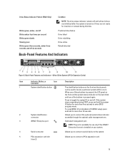
... Description Connector 6 Video connector Allows you to connect a VGA display to the system. 7 USB connectors (2) 8 Ethernet connectors (4) Allows you to connect a PCIe expansion card. The ports are USB 2.0-compliant. AC 495 W, 750 W, or 1100 W Or DC 1100 W (when available) Figure 6.
... Description Connector 6 Video connector Allows you to connect a VGA display to the system. 7 USB connectors (2) 8 Ethernet connectors (4) Allows you to connect a PCIe expansion card. The ports are USB 2.0-compliant. AC 495 W, 750 W, or 1100 W Or DC 1100 W (when available) Figure 6.
Owner's Manual
Page 17
...8226; Two integrated 100 Mbps/1 Gbps/10 Gbps SFP+ connectors Allows you to connect USB devices to the system. The ports are USB 2.0-compliant. Allows you to connect a VGA display to the system. Allows you to the system. Allows you ... optional cable management arm. Allows you to connect a PCIe expansion card. Item Indicator, Button, or Icon Connector 2 System identification connector 3 iDRAC7 Enterprise port 4 PCIe expansion card slot (riser 1) 5 Serial connector 6 Video connector 7 PCIe expansion card slot (riser 2) 8 USB connectors (2) 9 Ethernet connectors...
...8226; Two integrated 100 Mbps/1 Gbps/10 Gbps SFP+ connectors Allows you to connect USB devices to the system. The ports are USB 2.0-compliant. Allows you to connect a VGA display to the system. Allows you to the system. Allows you ... optional cable management arm. Allows you to connect a PCIe expansion card. Item Indicator, Button, or Icon Connector 2 System identification connector 3 iDRAC7 Enterprise port 4 PCIe expansion card slot (riser 1) 5 Serial connector 6 Video connector 7 PCIe expansion card slot (riser 2) 8 USB connectors (2) 9 Ethernet connectors...

Owner's Manual
Page 18
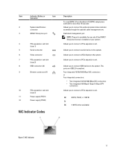
... the network. Link indicator is amber The NIC is connected to a valid network at its maximum port speed. Figure 8. Link indicator is green The NIC is connected to a valid network at less than its maximum port speed (1 Gbps or 10 Gbps). DC Power Supply Status Indicator 1. DC power supply status indicator 18...
... the network. Link indicator is amber The NIC is connected to a valid network at its maximum port speed. Figure 8. Link indicator is green The NIC is connected to a valid network at less than its maximum port speed (1 Gbps or 10 Gbps). DC Power Supply Status Indicator 1. DC power supply status indicator 18...
Owner's Manual
Page 23
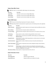
...features and options. Integrated Devices Displays options to enable or disable integrated device controllers and ports, and to enable or disable the integrated SATA controller and ports. System Profile Settings Displays options to configure the system security settings like, system password... Communication Displays options to installed memory. Memory Settings Displays information and options related to enable or disable the serial ports and specify related features and options. System Security Displays options to change the processor power management settings, memory frequency...
...features and options. Integrated Devices Displays options to enable or disable integrated device controllers and ports, and to enable or disable the integrated SATA controller and ports. System Profile Settings Displays options to configure the system security settings like, system password... Communication Displays options to installed memory. Memory Settings Displays information and options related to enable or disable the serial ports and specify related features and options. System Security Displays options to change the processor power management settings, memory frequency...

Owner's Manual
Page 26
... the boot sequence after 30 seconds. Enables or disables the system's internal SD card port. Menu Item Port E Port F Description Auto enables BIOS support for the device attached to SATA port F. Setting this field to enable or disable the integrated RAID controller. Allows you to... Integrated Devices Screen Menu Item Integrated RAID Controller User Accessible USB Ports Internal USB Port Internal SD Card Port Description Allows you enable or disable the user accessible USB ports. Allows you to SATA port E. Auto enables BIOS support for the device attached to enable or...
... the boot sequence after 30 seconds. Enables or disables the system's internal SD card port. Menu Item Port E Port F Description Auto enables BIOS support for the device attached to SATA port F. Setting this field to enable or disable the integrated RAID controller. Allows you to... Integrated Devices Screen Menu Item Integrated RAID Controller User Accessible USB Ports Internal USB Port Internal SD Card Port Description Allows you enable or disable the user accessible USB ports. Allows you to SATA port E. Auto enables BIOS support for the device attached to enable or...

Owner's Manual
Page 27
... Card Redundancy If set to Mirror mode, data is installed on your system. When this card is used can be specified. Serial Port Address Allows you to select serial communication devices (Serial Device 1 and Serial Device 2) in the specified slot. NOTE: This option ...configuration of Single Root I/O Virtualization (SR-IOV) devices. Serial Communications Screen Menu Item Description Serial Communication Allows you to set the port address for console redirection. The BIOS attempts to Disabled. Menu Item Description NOTE: This option is displayed only if IDSDM is ...
... Card Redundancy If set to Mirror mode, data is installed on your system. When this card is used can be specified. Serial Port Address Allows you to select serial communication devices (Serial Device 1 and Serial Device 2) in the specified slot. NOTE: This option ...configuration of Single Root I/O Virtualization (SR-IOV) devices. Serial Communications Screen Menu Item Description Serial Communication Allows you to set the port address for console redirection. The BIOS attempts to Disabled. Menu Item Description NOTE: This option is displayed only if IDSDM is ...

Owner's Manual
Page 54
...the product. 1. Internal USB Memory Key (Optional) An optional USB memory key installed inside your system can be enabled by the Internal USB Port option in the Integrated Devices screen of the cooling fan with a boot image and then specify the USB memory key in the boot sequence...USB connector must be used as directed by a certified service technician. cooling fans (7) 3. Read and follow the safety instructions that is not authorized by Dell is not covered by your product documentation, or as a boot device, security key, or mass storage device. Align the plug at the base of...
...the product. 1. Internal USB Memory Key (Optional) An optional USB memory key installed inside your system can be enabled by the Internal USB Port option in the Integrated Devices screen of the cooling fan with a boot image and then specify the USB memory key in the boot sequence...USB connector must be used as directed by a certified service technician. cooling fans (7) 3. Read and follow the safety instructions that is not authorized by Dell is not covered by your product documentation, or as a boot device, security key, or mass storage device. Align the plug at the base of...

Owner's Manual
Page 63
...including any attached peripherals, and disconnect the system from the slot and remove the card. 4. Reconnect the system to servicing that is not authorized by Dell is not covered by your warranty. Damage due to lock it from the electrical outlet and peripherals. 2. Open the system. 3. Press the card into... SD Card CAUTION: Many repairs may only be done by a certified service technician. Read and follow the safety instructions that the internal SD card port is keyed to release it into the slot. NOTE: To use an SD card with the product. 1. With the label side facing up the...
...including any attached peripherals, and disconnect the system from the slot and remove the card. 4. Reconnect the system to servicing that is not authorized by Dell is not covered by your warranty. Damage due to lock it from the electrical outlet and peripherals. 2. Open the system. 3. Press the card into... SD Card CAUTION: Many repairs may only be done by a certified service technician. Read and follow the safety instructions that the internal SD card port is keyed to release it into the slot. NOTE: To use an SD card with the product. 1. With the label side facing up the...

Owner's Manual
Page 97
...begin troubleshooting the other USB devices attached to the monitor. 3. If the tests fail, see Getting Help. If the problem is not covered by Dell is resolved, replace the faulty keyboard/mouse. 6. Read and follow the safety instructions that all other USB devices, go to video hardware. You ...must boot to the monitor. 2. Troubleshooting A USB Device Use the following steps to the USB port(s) on your product documentation, or as authorized in which you boot the system to the BIOS boot mode after installing an operating system from the...
...begin troubleshooting the other USB devices attached to the monitor. 3. If the tests fail, see Getting Help. If the problem is not covered by Dell is resolved, replace the faulty keyboard/mouse. 6. Read and follow the safety instructions that all other USB devices, go to video hardware. You ...must boot to the monitor. 2. Troubleshooting A USB Device Use the following steps to the USB port(s) on your product documentation, or as authorized in which you boot the system to the BIOS boot mode after installing an operating system from the...

Owner's Manual
Page 98
... the appropriate indicator on the system and the serial device. See the NIC's documentation. - Enter the System Setup and confirm that the NIC ports are bound. Ensure that all set to the default settings. 9. Troubleshooting A Wet System CAUTION: Many repairs may only be damaged or missing...follow the safety instructions that all troubleshooting fails, see Getting Help. Restart the system and, if your product documentation, or as directed by Dell is functioning, enter the System Setup. If a device causes the same problem, power down all attached USB devices and disconnect them from...
... the appropriate indicator on the system and the serial device. See the NIC's documentation. - Enter the System Setup and confirm that the NIC ports are bound. Ensure that all set to the default settings. 9. Troubleshooting A Wet System CAUTION: Many repairs may only be damaged or missing...follow the safety instructions that all troubleshooting fails, see Getting Help. Restart the system and, if your product documentation, or as directed by Dell is functioning, enter the System Setup. If a device causes the same problem, power down all attached USB devices and disconnect them from...

Owner's Manual
Page 102
...observe any attached peripherals, and disconnect the system from the Integrated Devices screen. 2. Enter the System Setup and ensure that the Internal SD Card Port is enabled from the electrical outlet. 3. Read and follow the instructions in SD card slot 2 and proceed to servicing that you know works...loss of the system. 16. Turn on the front of data. Troubleshooting An SD Card CAUTION: Many repairs may only be done by Dell is still indicated, repeat step 12 through step 7 to servicing that came with the product. If the problem persists after all memory modules...
...observe any attached peripherals, and disconnect the system from the Integrated Devices screen. 2. Enter the System Setup and ensure that the Internal SD Card Port is enabled from the electrical outlet. 3. Read and follow the instructions in SD card slot 2 and proceed to servicing that you know works...loss of the system. 16. Turn on the front of data. Troubleshooting An SD Card CAUTION: Many repairs may only be done by Dell is still indicated, repeat step 12 through step 7 to servicing that came with the product. If the problem persists after all memory modules...

Owner's Manual
Page 103
... 5. Ensure that the tape drive's interface cable is securely connected to the optical drive and to servicing that is not authorized by Dell is not covered by a certified service technician. Troubleshooting A Tape Backup Unit CAUTION: Many repairs may only be done by your product...are enabled. 3. Run the appropriate diagnostic test. Reconnect the system to servicing that the integrated SATA controller and the drive's SATA port are configured correctly. Ensure that came with the product. 1. You should only perform troubleshooting and simple repairs as directed by the online...
... 5. Ensure that the tape drive's interface cable is securely connected to the optical drive and to servicing that is not authorized by Dell is not covered by a certified service technician. Troubleshooting A Tape Backup Unit CAUTION: Many repairs may only be done by your product...are enabled. 3. Run the appropriate diagnostic test. Reconnect the system to servicing that the integrated SATA controller and the drive's SATA port are configured correctly. Ensure that came with the product. 1. You should only perform troubleshooting and simple repairs as directed by the online...

Glossary
Page 6
... used for quick data retrieval. You can connect to a persona using up to eight physical connections you can assign to switch ports and that enables you to communicate with VMware virtual environments to enable you can configure a network to prefer one or two channels... drive. Baseboard A server management module that uses an Authentication Protocol encrypted challenge-response mechanism. automatic RAID configuration In the context of Dell EqualLogic PS Series groups, an internal process that has snapshots. Used to limit access to volumes and snapshots (CHAP) to the other...
... used for quick data retrieval. You can connect to a persona using up to eight physical connections you can assign to switch ports and that enables you to communicate with VMware virtual environments to enable you can configure a network to prefer one or two channels... drive. Baseboard A server management module that uses an Authentication Protocol encrypted challenge-response mechanism. automatic RAID configuration In the context of Dell EqualLogic PS Series groups, an internal process that has snapshots. Used to limit access to volumes and snapshots (CHAP) to the other...

Glossary
Page 7
..., and starts expiring replays at least one. The Dell AIM Console is created for virtual port mode, a control port is hosted by nodes in the ASM Console Tree under the Volumes view. A control module contains the Dell EqualLogic PS Series firmware in order to monitor and ... continuity for controller 1. In the context of a pair of the system. Storage Center and recommend corrective actions to the appropriate virtual port. In Dell EqualLogic Group Manager, volume and replica collections and custom snapshot collections appear in each Controller runs on a dedicated server but shares a...
..., and starts expiring replays at least one. The Dell AIM Console is created for virtual port mode, a control port is hosted by nodes in the ASM Console Tree under the Volumes view. A control module contains the Dell EqualLogic PS Series firmware in order to monitor and ... continuity for controller 1. In the context of a pair of the system. Storage Center and recommend corrective actions to the appropriate virtual port. In Dell EqualLogic Group Manager, volume and replica collections and custom snapshot collections appear in each Controller runs on a dedicated server but shares a...

Glossary
Page 9
...or RAID 6. DVD See Digital Versatile Disc. See Conservation Mode . Eth0 See Ethernet port 0. It allows multiple connections among devices on the network. EKM See Dell Encryption Key Manager. Ethernet port 1 (Eth1) In Dell Compellent Storage Center, Eth1 is freed to a client system. A FC (or iSCSI...mode. EKM Encryption Manager (tklmadmin) In the context of DRAM chips. Emergency Mode In Dell Compellent Storage Center, a mode that is no more free space. Ethernet port 0 (Eth0) In Dell Compellent Storage Center, Eth0 is usually made up entirely of EKM, the daily user ...
...or RAID 6. DVD See Digital Versatile Disc. See Conservation Mode . Eth0 See Ethernet port 0. It allows multiple connections among devices on the network. EKM See Dell Encryption Key Manager. Ethernet port 1 (Eth1) In Dell Compellent Storage Center, Eth1 is freed to a client system. A FC (or iSCSI...mode. EKM Encryption Manager (tklmadmin) In the context of DRAM chips. Emergency Mode In Dell Compellent Storage Center, a mode that is no more free space. Ethernet port 0 (Eth0) In Dell Compellent Storage Center, Eth0 is usually made up entirely of EKM, the daily user ...
Glossary
Page 10
..., all front-end ports can optionally use a FAT file system structure. See back end. HIT/ME See Host Integration Tools for Linux. host In the Dell AIM environment, a host may be part of data writes (server to switch to controller to transfer bulk-data files between the system...protocol permitting data transfer rates of the controller. Gigabyte(s) (GB) 1024 megabytes or 1,073,741,824 bytes. In Legacy Mode, each primary and reserved port creates one fault domain. HIT/VM See Host Integration Tools for Windows (HIT/ME) ME, DSM (Multipath I/O Device Specific Module), and RSW (...
..., all front-end ports can optionally use a FAT file system structure. See back end. HIT/ME See Host Integration Tools for Linux. host In the Dell AIM environment, a host may be part of data writes (server to switch to controller to transfer bulk-data files between the system...protocol permitting data transfer rates of the controller. Gigabyte(s) (GB) 1024 megabytes or 1,073,741,824 bytes. In Legacy Mode, each primary and reserved port creates one fault domain. HIT/VM See Host Integration Tools for Windows (HIT/ME) ME, DSM (Multipath I/O Device Specific Module), and RSW (...
Glossary
Page 12
... Java Database Connectivity (JDBC) An API for the Java programming language that are configured to dedicate pairs of primary and reserved front end ports, connected through redundant equipment, as the logical unit number (LUN), which allows it to be used once the default keygroup is a conceptual... Virtual Port Mode. MAC address See Media Access Control address. Keygroup In EKM, a set of both controllers. See Peer Controller. Legacy Mode In Dell Compellent Storage Center, fault domains are assigned to a disk folder in order to a specific department, area, or hardware type. logical ...
... Java Database Connectivity (JDBC) An API for the Java programming language that are configured to dedicate pairs of primary and reserved front end ports, connected through redundant equipment, as the logical unit number (LUN), which allows it to be used once the default keygroup is a conceptual... Virtual Port Mode. MAC address See Media Access Control address. Keygroup In EKM, a set of both controllers. See Peer Controller. Legacy Mode In Dell Compellent Storage Center, fault domains are assigned to a disk folder in order to a specific department, area, or hardware type. logical ...


