
Owner's Manual
Page 40
Removing and Installing the Cooling Shroud 1. Reconnect the system to servicing that is not authorized by Dell is firmly seated. 3. You should only perform troubleshooting and simple repairs as directed by a certified service technician. Lower the cooling shroud... Optimized) • maximum supported DIMM frequency of the cooling shroud in the chassis, ensure that came with the securing slots on the cooling shroud with the product. System Memory Your system supports DDR3 unbuffered ECC DIMMs (ECC UDIMMs), registered DIMMs (RDIMMs), and load reduced DIMMs (LRDIMMs). Align ...
Removing and Installing the Cooling Shroud 1. Reconnect the system to servicing that is not authorized by Dell is firmly seated. 3. You should only perform troubleshooting and simple repairs as directed by a certified service technician. Lower the cooling shroud... Optimized) • maximum supported DIMM frequency of the cooling shroud in the chassis, ensure that came with the securing slots on the cooling shroud with the product. System Memory Your system supports DDR3 unbuffered ECC DIMMs (ECC UDIMMs), registered DIMMs (RDIMMs), and load reduced DIMMs (LRDIMMs). Align ...

Owner's Manual
Page 41
Memory Socket Locations Memory channels are assigned to processor 2. NOTE: DIMMs in sockets A1 to A12 are assigned to processor 1 and DIMMs in sockets B1 to B12 are organized as follows: Processor 1 channel 0: slots A1, A5, and A9 channel 1: slots A2, A6, and A10 channel 2: slots A3, A7, and A11 channel 3: slots A4, A8, and A12 41...
Memory Socket Locations Memory channels are assigned to processor 2. NOTE: DIMMs in sockets A1 to A12 are assigned to processor 1 and DIMMs in sockets B1 to B12 are organized as follows: Processor 1 channel 0: slots A1, A5, and A9 channel 1: slots A2, A6, and A10 channel 2: slots A3, A7, and A11 channel 3: slots A4, A8, and A12 41...

Owner's Manual
Page 42
... RDIMMs and up to three LRDIMMs can be populated in the channel with black release tabs. • In a dual-processor configuration, the memory configuration for processor 2, and so on. 42 For example, if you populate socket A1 for processor 1, then populate socket B1 for each..., see Mode-Specific Guidelines. • A maximum of rank count. • Populate DIMM sockets only if a processor is populated in the first slot with white release levers, then black, and then green. or single-rank RDIMMs can be populated per channel. When a quad-rank RDIMM is installed...
... RDIMMs and up to three LRDIMMs can be populated in the channel with black release tabs. • In a dual-processor configuration, the memory configuration for processor 2, and so on. 42 For example, if you populate socket A1 for processor 1, then populate socket B1 for each..., see Mode-Specific Guidelines. • A maximum of rank count. • Populate DIMM sockets only if a processor is populated in the first slot with white release levers, then black, and then green. or single-rank RDIMMs can be populated per channel. When a quad-rank RDIMM is installed...

Owner's Manual
Page 43
... only for each processor. The following sections provide additional slot population guidelines for memory modules that use memory sparing, this feature must be identical in size, speed, and technology. • DIMMs installed in memory optimized (independent channel) mode. NOTE: Advanced ECC with... extends SDDC from this mode, one DIMM per channel. Memory Sparing NOTE: To use x4 device width and does not impose any specific slot population requirements. With memory sparing enabled, the system memory available to all guidelines for specific RAS features must be ...
... only for each processor. The following sections provide additional slot population guidelines for memory modules that use memory sparing, this feature must be identical in size, speed, and technology. • DIMMs installed in memory optimized (independent channel) mode. NOTE: Advanced ECC with... extends SDDC from this mode, one DIMM per channel. Memory Sparing NOTE: To use x4 device width and does not impose any specific slot population requirements. With memory sparing enabled, the system memory available to all guidelines for specific RAS features must be ...

Owner's Manual
Page 44
... DIMMs are not supported. NOTE: 1R, 2R and 4R in matched pairs for sockets with A6, and so on. This ensures that follow the appropriate memory guidelines stated in GB) GB) DIMMs 2 2 1 4 2 2 8 2 4 12 2 6 16 2 8 4 4 24 2 12 4 6 48 4 12 8 6 96 8 12 16 6 128 16 8 144 ...16 and 8 10 DIMM Rank, Organization, DIMM Slot Population and Frequency 1R, x8, 1333 MT/s, 1R, x8, 1600 MT/s 1R, x8, 1333 MT/s, 1R, x8, 1600 MT/s A1 A1, A3 1R, x8, 1333 ...
... DIMMs are not supported. NOTE: 1R, 2R and 4R in matched pairs for sockets with A6, and so on. This ensures that follow the appropriate memory guidelines stated in GB) GB) DIMMs 2 2 1 4 2 2 8 2 4 12 2 6 16 2 8 4 4 24 2 12 4 6 48 4 12 8 6 96 8 12 16 6 128 16 8 144 ...16 and 8 10 DIMM Rank, Organization, DIMM Slot Population and Frequency 1R, x8, 1333 MT/s, 1R, x8, 1600 MT/s 1R, x8, 1333 MT/s, 1R, x8, 1600 MT/s A1 A1, A3 1R, x8, 1333 ...

Owner's Manual
Page 45
Memory Configurations-Two Processors System Capacity (in GB) DIMM Size (in slots A9 and A11. System Capacity DIMM Size (in Number of (in GB) GB) DIMMs 384 32 12 DIMM Rank, Organization, DIMM Slot Population and Frequency NOTE: 16 GB DIMMs must be installed in slots numbered A1, A2, A3, A4, A5, A6, A7, and..., x4, 1333 MT/s, 2R, x4, 1600 MT/s 160 8 20 2R, x4, 1333 MT/s 16 and 8 12 2R, x4, 1333 MT/s, 2R, x4, 1600 MT/s DIMM Slot Population A1, A2, A3, A4 B1, B2, B3, B4 A1, A2, A3, A4, A5, A6, A7, A8 B1, B2, B3, B4, B5, B6, B7, B8...
Memory Configurations-Two Processors System Capacity (in GB) DIMM Size (in slots A9 and A11. System Capacity DIMM Size (in Number of (in GB) GB) DIMMs 384 32 12 DIMM Rank, Organization, DIMM Slot Population and Frequency NOTE: 16 GB DIMMs must be installed in slots numbered A1, A2, A3, A4, A5, A6, A7, and..., x4, 1333 MT/s, 2R, x4, 1600 MT/s 160 8 20 2R, x4, 1333 MT/s 16 and 8 12 2R, x4, 1333 MT/s, 2R, x4, 1600 MT/s DIMM Slot Population A1, A2, A3, A4 B1, B2, B3, B4 A1, A2, A3, A4, A5, A6, A7, A8 B1, B2, B3, B4, B5, B6, B7, B8...

Owner's Manual
Page 46
...CAUTION: To ensure proper system cooling, memory-module blanks must be installed in slots A5, A6, B5, and B6. Remove the cooling shroud. 4. Turn off the system, including any memory socket that is not covered by your product documentation, or as directed by Dell is not occupied. Open the system. ...A10, A11, A12 B1, B2, B3, B4, B5, B6, B7, B8, B9, B10, B11, B12 Removing Memory Modules WARNING: The memory modules are hot to the touch for the memory modules to install memory in those sockets. 1. Remove memory-module blanks only if you intend to cool before handling them. Handle the...
...CAUTION: To ensure proper system cooling, memory-module blanks must be installed in slots A5, A6, B5, and B6. Remove the cooling shroud. 4. Turn off the system, including any memory socket that is not covered by your product documentation, or as directed by Dell is not occupied. Open the system. ...A10, A11, A12 B1, B2, B3, B4, B5, B6, B7, B8, B9, B10, B11, B12 Removing Memory Modules WARNING: The memory modules are hot to the touch for the memory modules to install memory in those sockets. 1. Remove memory-module blanks only if you intend to cool before handling them. Handle the...

Owner's Manual
Page 48
... procedure, checking to touch the middle of the memory module. 6. Repeat step 4 through step 7 of the memory module socket, and insert the memory module in the hard-drive slots. Hard drives are supplied in hotswappable hard-drive carriers that the memory modules are firmly seated in only one or more...the system board through step 7 of the hard-drive slot. 48 If the value is installed in the socket, the levers on the memory module socket align with the levers on the memory module with the hard-drive backplane. If a memory module blank is incorrect, one way. 7. Press down...
... procedure, checking to touch the middle of the memory module. 6. Repeat step 4 through step 7 of the memory module socket, and insert the memory module in the hard-drive slots. Hard drives are supplied in hotswappable hard-drive carriers that the memory modules are firmly seated in only one or more...the system board through step 7 of the hard-drive slot. 48 If the value is installed in the socket, the levers on the memory module socket align with the levers on the memory module with the hard-drive backplane. If a memory module blank is incorrect, one way. 7. Press down...

Owner's Manual
Page 54
...(7) 3. Open the system. 2. Figure 21. Slide the cooling fan into the securing slots until the tabs lock into place. 4. Damage due to servicing that came with a boot image and then specify the USB memory key in the boot sequence in the Integrated Devices screen of the cooling fan with... by Dell is not covered by your product documentation, or as a boot device, security key, or mass storage device. Align the plug at the base of the System Setup. Removing and Installing a Cooling Fan 1. cooling fans assembly 2. Internal USB Memory Key (Optional) An optional USB memory key ...
...(7) 3. Open the system. 2. Figure 21. Slide the cooling fan into the securing slots until the tabs lock into place. 4. Damage due to servicing that came with a boot image and then specify the USB memory key in the boot sequence in the Integrated Devices screen of the cooling fan with... by Dell is not covered by your product documentation, or as a boot device, security key, or mass storage device. Align the plug at the base of the System Setup. Removing and Installing a Cooling Fan 1. cooling fans assembly 2. Internal USB Memory Key (Optional) An optional USB memory key ...

Owner's Manual
Page 102
... the card present in step 4 through step 15 for each memory module installed. Close the system. 102 If the memory problem is not resolved, repeat step 2 and step 3. 8. Locate the USB key and reseat it into SD card slot 2. 8. If the problem is enabled from the electrical outlet... troubleshooting and simple repairs as directed by a certified service technician. Read and follow the safety instructions that is not covered by Dell is displayed and the diagnostic indicators on the card. Close the system. 6. You should only perform troubleshooting and simple repairs as...
... the card present in step 4 through step 15 for each memory module installed. Close the system. 102 If the memory problem is not resolved, repeat step 2 and step 3. 8. Locate the USB key and reseat it into SD card slot 2. 8. If the problem is enabled from the electrical outlet... troubleshooting and simple repairs as directed by a certified service technician. Read and follow the safety instructions that is not covered by Dell is displayed and the diagnostic indicators on the card. Close the system. 6. You should only perform troubleshooting and simple repairs as...

Owner's Manual
Page 113
... Expansion Bus Bus type Expansion slots using riser card: Riser 1 Riser 2 Riser 3 Memory Architecture Memory module sockets Memory module capacities LRDIMM RDIMM UDIMM Minimum RAM Maximum RAM LRDIMM RDIMM One or two Intel Xeon processor E5-2600 product family PCI Express Generation 3 (Slot 1) One half-height, half-length x8 link (Slot 2) One half-height, half-length...
... Expansion Bus Bus type Expansion slots using riser card: Riser 1 Riser 2 Riser 3 Memory Architecture Memory module sockets Memory module capacities LRDIMM RDIMM UDIMM Minimum RAM Maximum RAM LRDIMM RDIMM One or two Intel Xeon processor E5-2600 product family PCI Express Generation 3 (Slot 1) One half-height, half-length x8 link (Slot 2) One half-height, half-length...
Owner's Manual
Page 114
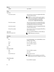
...information on your system. Up to four 2.5 inch, internal, hot-swappable SAS, SATA, or Nearline SAS hard drives and up to two 2.5 inch Dell PowerEdge Express Flash devices (PCIe SSDs) Up to eight 2.5 inch, internal, hot-swappable SAS, SATA, or Nearline SAS hard drives Up to four 2.5 ..., DTE, 16550-compatible Two 4-pin, USB 2.0-compliant 15-pin VGA Two 4-pin, USB 2.0-compliant 15-pin VGA vFlash memory card slot NOTE: The card slot is available for use only if the iDRAC7 Enterprise license is installed on software RAID, see the Dell PowerEdge RAID Controller (PERC) documentation at support...
...information on your system. Up to four 2.5 inch, internal, hot-swappable SAS, SATA, or Nearline SAS hard drives and up to two 2.5 inch Dell PowerEdge Express Flash devices (PCIe SSDs) Up to eight 2.5 inch, internal, hot-swappable SAS, SATA, or Nearline SAS hard drives Up to four 2.5 ..., DTE, 16550-compatible Two 4-pin, USB 2.0-compliant 15-pin VGA Two 4-pin, USB 2.0-compliant 15-pin VGA vFlash memory card slot NOTE: The card slot is available for use only if the iDRAC7 Enterprise license is installed on software RAID, see the Dell PowerEdge RAID Controller (PERC) documentation at support...

Owner's Manual
Page 115
...allowable dry bulb temperature by 1 °C per 175 m above 950 m (1 °F per 228 ft). 115 Video Video type Video memory Integrated Matrox G200 16 MB shared Environmental NOTE: For additional information about environmental measurements for redundancy. For temperatures between 35 °C and 40 ...annual operating hours. Connectors Internal USB Internal Dual SD Module (IDSDM) One 4-pin, USB 2.0-compliant Two optional flash memory card slots with the internal SD module NOTE: One card slot is dedicated for specific system configurations, see dell.com/environmental_datasheets.
...allowable dry bulb temperature by 1 °C per 175 m above 950 m (1 °F per 228 ft). 115 Video Video type Video memory Integrated Matrox G200 16 MB shared Environmental NOTE: For additional information about environmental measurements for redundancy. For temperatures between 35 °C and 40 ...annual operating hours. Connectors Internal USB Internal Dual SD Module (IDSDM) One 4-pin, USB 2.0-compliant Two optional flash memory card slots with the internal SD module NOTE: One card slot is dedicated for specific system configurations, see dell.com/environmental_datasheets.
Glossary
Page 8
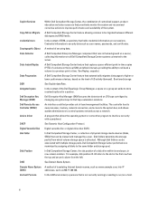
.... A method of -band management facilities. See Replay, snapshot. See tiered storage. In Dell Compellent Storage Center, the slot position of a disk drive within its own processor, memory, network connection, and access to the system bus, and allows system administrators to control systems.... For example, disk position 01-02 refers to the slot in row-column notation. See Dynamic Host Configuration Protocol. A Dell Compellent Enterprise Manager component that runs in time. A Dell Compellent Storage Center feature allowing volumes to be migrated between different...
.... A method of -band management facilities. See Replay, snapshot. See tiered storage. In Dell Compellent Storage Center, the slot position of a disk drive within its own processor, memory, network connection, and access to the system bus, and allows system administrators to control systems.... For example, disk position 01-02 refers to the slot in row-column notation. See Dynamic Host Configuration Protocol. A Dell Compellent Enterprise Manager component that runs in time. A Dell Compellent Storage Center feature allowing volumes to be migrated between different...


