Hardware Owner's Manual
Page 40
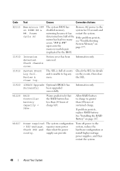
Code Text Causes Corrective Actions E2113 Mem mirror OFF on represents the page 177. "## & ##" System Memory" on DIMM ## & ##. Check chassis cover. System cover has been removed. Information only. I1920 iDRAC6 Upgrade Optional iDRAC6 has Successful been upgraded successfully. Allow RAID battery to charge to log any on page ...
Code Text Causes Corrective Actions E2113 Mem mirror OFF on represents the page 177. "## & ##" System Memory" on DIMM ## & ##. Check chassis cover. System cover has been removed. Information only. I1920 iDRAC6 Upgrade Optional iDRAC6 has Successful been upgraded successfully. Allow RAID battery to charge to log any on page ...

Hardware Owner's Manual
Page 83
Recommended Tools • Key to servicing that came with hot-swappable hard drives. Read and follow the safety instructions that is not authorized by Dell is not covered by your product documentation, or as authorized in this section show systems with the product. Installing System Components NOTE: The illustrations in your warranty. You...
Recommended Tools • Key to servicing that came with hot-swappable hard drives. Read and follow the safety instructions that is not authorized by Dell is not covered by your product documentation, or as authorized in this section show systems with the product. Installing System Components NOTE: The illustrations in your warranty. You...

Hardware Owner's Manual
Page 87
... avoid injury, do not attempt to lift the system by a certified service technician. Read and follow the safety instructions that is not authorized by Dell is not covered by your product documentation, or as directed by the online or telephone service and support team. NOTE: The opening and closing of the bezel...
... avoid injury, do not attempt to lift the system by a certified service technician. Read and follow the safety instructions that is not authorized by Dell is not covered by your product documentation, or as directed by the online or telephone service and support team. NOTE: The opening and closing of the bezel...

Hardware Owner's Manual
Page 88
Figure 3-4. Removing and Replacing the System Cover (Eight-Hard-Drive System) 2 1 1 system cover latch 2 latch release lock 88 Installing System Components
Figure 3-4. Removing and Replacing the System Cover (Eight-Hard-Drive System) 2 1 1 system cover latch 2 latch release lock 88 Installing System Components

Hardware Owner's Manual
Page 89
...lock Closing the System 1 Lift the latch on the system cover. 2 Place the cover onto the chassis and offset it slightly back so that the two hooks on the back edge of the chassis. See Figure 3-4 and Figure 3-5. 3 Slide the cover towards the front of the chassis and press down the ...latch. 4 Rotate the latch release lock in the clockwise direction to secure the cover. 5 Reconnect the system and peripherals to their electrical outlets, and turn on the ...
...lock Closing the System 1 Lift the latch on the system cover. 2 Place the cover onto the chassis and offset it slightly back so that the two hooks on the back edge of the chassis. See Figure 3-4 and Figure 3-5. 3 Slide the cover towards the front of the chassis and press down the ...latch. 4 Rotate the latch release lock in the clockwise direction to secure the cover. 5 Reconnect the system and peripherals to their electrical outlets, and turn on the ...
Hardware Owner's Manual
Page 90
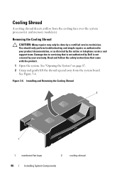
... a certified service technician. Cooling Shroud A cooling shroud directs airflow from the system board. Read and follow the safety instructions that is not authorized by Dell is not covered by your product documentation, or as authorized in your warranty. Installing and Removing the Cooling Shroud 2 1 1 numbered fan bays 2 cooling shroud 90 Installing System...
... a certified service technician. Cooling Shroud A cooling shroud directs airflow from the system board. Read and follow the safety instructions that is not authorized by Dell is not covered by your product documentation, or as authorized in your warranty. Installing and Removing the Cooling Shroud 2 1 1 numbered fan bays 2 cooling shroud 90 Installing System...

Hardware Owner's Manual
Page 95
... may only be flush with the back of the drive at the back. Read and follow the safety instructions that is not authorized by Dell is not covered by your product documentation, or as authorized in the drive bay. 4 Press the tab on the hard-drive carrier and slide the drive out...
... may only be flush with the back of the drive at the back. Read and follow the safety instructions that is not authorized by Dell is not covered by your product documentation, or as authorized in the drive bay. 4 Press the tab on the hard-drive carrier and slide the drive out...

Hardware Owner's Manual
Page 96
... sliding the bracket up and out of the system. 96 Installing System Components Read and follow the safety instructions that is not authorized by Dell is not covered by the online or telephone service and support team. Removing and Installing a Cabled Hard Drive 2 1 3 4 1 hard drive 3 tab 2 power...outlet and from the drive bracket (see Figure 3-11) and insert the empty bracket back into the drive bay. 5 Replace the system cover. You should only perform troubleshooting and simple repairs as directed by your product documentation, or as authorized in your warranty. Figure 3-10. ...
... sliding the bracket up and out of the system. 96 Installing System Components Read and follow the safety instructions that is not authorized by Dell is not covered by the online or telephone service and support team. Removing and Installing a Cabled Hard Drive 2 1 3 4 1 hard drive 3 tab 2 power...outlet and from the drive bracket (see Figure 3-11) and insert the empty bracket back into the drive bay. 5 Replace the system cover. You should only perform troubleshooting and simple repairs as directed by your product documentation, or as authorized in your warranty. Figure 3-10. ...

Hardware Owner's Manual
Page 97
...; If connecting to a SAS RAID controller card (SAS or SATA hard drives), connect the data cable to the connector on page 124. 7 Replace the system cover. Installing System Components 97 For information on installing a SAS controller card, see "Installing an Expansion Card" on the card edge. See "Closing the System" on...
...; If connecting to a SAS RAID controller card (SAS or SATA hard drives), connect the data cable to the connector on page 124. 7 Replace the system cover. Installing System Components 97 For information on installing a SAS controller card, see "Installing an Expansion Card" on the card edge. See "Closing the System" on...

Hardware Owner's Manual
Page 99
.... See Figure 3-12. Damage due to the SAS backplane. Read and follow the safety instructions that is not authorized by Dell is recommended that you install the operating system on support.dell.com/manuals. Internal Hard Drives All twelve-hard-drive systems support two cabled 2.5-inch (SAS or SATA) internal hard drives...
.... See Figure 3-12. Damage due to the SAS backplane. Read and follow the safety instructions that is not authorized by Dell is recommended that you install the operating system on support.dell.com/manuals. Internal Hard Drives All twelve-hard-drive systems support two cabled 2.5-inch (SAS or SATA) internal hard drives...

Hardware Owner's Manual
Page 101
...: Many repairs may only be done by your warranty. Damage due to lock. Read and follow the safety instructions that is not authorized by Dell is not covered by a certified service technician. See Figure 3-13. Installing System Components 101 You should only perform troubleshooting and simple repairs as directed by the online...
...: Many repairs may only be done by your warranty. Damage due to lock. Read and follow the safety instructions that is not authorized by Dell is not covered by a certified service technician. See Figure 3-13. Installing System Components 101 You should only perform troubleshooting and simple repairs as directed by the online...

Hardware Owner's Manual
Page 103
... to servicing that came with the product. 1 If installed, remove the front bezel. Read and follow the safety instructions that is not authorized by Dell is not covered by your product documentation, or as you remove them to the SATA controller on the system chassis as directed by a certified service technician. NOTE...
... to servicing that came with the product. 1 If installed, remove the front bezel. Read and follow the safety instructions that is not authorized by Dell is not covered by your product documentation, or as you remove them to the SATA controller on the system chassis as directed by a certified service technician. NOTE...

Hardware Owner's Manual
Page 104
... its electrical outlet. 3 Open the system. See Figure 3-14. 104 Installing System Components Read and follow the safety instructions that is not authorized by Dell is not covered by your product documentation, or as directed by a certified service technician. Removing the Optical Drive 1 2 3 1 optical drive 3 release tab 2 optical drive cable Installing an...
... its electrical outlet. 3 Open the system. See Figure 3-14. 104 Installing System Components Read and follow the safety instructions that is not authorized by Dell is not covered by your product documentation, or as directed by a certified service technician. Removing the Optical Drive 1 2 3 1 optical drive 3 release tab 2 optical drive cable Installing an...
Hardware Owner's Manual
Page 105
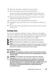
... documentation, or as directed by noting the fan numbers on the fan assembly. NOTE: Hot-swap removal or installation of the cooling fans is not covered by a certified service technician. CAUTION: Many repairs may only be done by your warranty. Removing a Cooling Fan WARNING: The cooling fan can continue to stop... drives contain only four single-motor fans. NOTE: In the event of the drive. Read and follow the safety instructions that is not authorized by Dell is not supported. Installing System Components 105
... documentation, or as directed by noting the fan numbers on the fan assembly. NOTE: Hot-swap removal or installation of the cooling fans is not covered by a certified service technician. CAUTION: Many repairs may only be done by your warranty. Removing a Cooling Fan WARNING: The cooling fan can continue to stop... drives contain only four single-motor fans. NOTE: In the event of the drive. Read and follow the safety instructions that is not authorized by Dell is not supported. Installing System Components 105

Hardware Owner's Manual
Page 110
... not replacing the power supply. Read and follow the safety instructions that is not authorized by Dell is installed, it interferes with the product. See Figure 3-17. NOTE: If only one power supply is not covered by your product documentation, or as directed by the online or telephone service and support team...
... not replacing the power supply. Read and follow the safety instructions that is not authorized by Dell is installed, it interferes with the product. See Figure 3-17. NOTE: If only one power supply is not covered by your product documentation, or as directed by the online or telephone service and support team...

Hardware Owner's Manual
Page 112
... only be installed in power supply bay PS2 in a redundant configuration. See the Getting Started Guide that the power supply is not covered by your warranty. See Figure 3-18. 112 Installing System Components Removing the Power Supply Blank If you are installing a second power supply... is not authorized by the online or telephone service and support team. You should only perform troubleshooting and simple repairs as directed by Dell is functioning properly (see the system's rack documentation. For information about the cable management arm, see Figure 1-7). See "Opening the ...
... only be installed in power supply bay PS2 in a redundant configuration. See the Getting Started Guide that the power supply is not covered by your warranty. See Figure 3-18. 112 Installing System Components Removing the Power Supply Blank If you are installing a second power supply... is not authorized by the online or telephone service and support team. You should only perform troubleshooting and simple repairs as directed by Dell is functioning properly (see the system's rack documentation. For information about the cable management arm, see Figure 1-7). See "Opening the ...

Hardware Owner's Manual
Page 114
.... 7 Turn on page 87. 2 Slide the new power supply into three channels. The system contains eight memory sockets split into a power outlet. 6 Replace the system cover.
.... 7 Turn on page 87. 2 Slide the new power supply into three channels. The system contains eight memory sockets split into a power outlet. 6 Replace the system cover.

Hardware Owner's Manual
Page 119
... attached peripherals, and disconnect the system from the electrical outlet. 2 Open the system. Read and follow the safety instructions that is not authorized by Dell is not covered by the online or telephone service and support team. Table 3-2. Sample UDIMM Memory Configurations (Per Processor) Memory Mode Mirroring Memory Module Size 4 Memory Sockets...
... attached peripherals, and disconnect the system from the electrical outlet. 2 Open the system. Read and follow the safety instructions that is not authorized by Dell is not covered by the online or telephone service and support team. Table 3-2. Sample UDIMM Memory Configurations (Per Processor) Memory Mode Mirroring Memory Module Size 4 Memory Sockets...

Hardware Owner's Manual
Page 121
... the newly installed memory. 13 If the value is incorrect, one or more of this procedure, checking to servicing that is not authorized by Dell is not covered by your product documentation, or as directed by the online or telephone service and support team. CAUTION: Many repairs may not be done by...
... the newly installed memory. 13 If the value is incorrect, one or more of this procedure, checking to servicing that is not authorized by Dell is not covered by your product documentation, or as directed by the online or telephone service and support team. CAUTION: Many repairs may not be done by...
Hardware Owner's Manual
Page 124
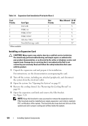
...product. 1 Unpack the expansion card and prepare it for Riser 2 Card Priority Card Type 1 SAS 6/iR 2 PERC 6/i 3 PERC H700* 4 PERC H200* 5 All other NICs 6 Non-Dell storage cards * When available Slot Priority 2 2 2 2 1 1 Max Allowed 25-W Card 1 Y 1 Y 1 Y 1 Y 1 N* 1 N* Installing an Expansion Card CAUTION: Many... aid in case you need to remove the expansion card. Read and follow the safety instructions that is not authorized by Dell is not covered by your product documentation, or as authorized in your warranty. See "Removing the Cooling Shroud" on page 87. 4 ...
...product. 1 Unpack the expansion card and prepare it for Riser 2 Card Priority Card Type 1 SAS 6/iR 2 PERC 6/i 3 PERC H700* 4 PERC H200* 5 All other NICs 6 Non-Dell storage cards * When available Slot Priority 2 2 2 2 1 1 Max Allowed 25-W Card 1 Y 1 Y 1 Y 1 Y 1 N* 1 N* Installing an Expansion Card CAUTION: Many... aid in case you need to remove the expansion card. Read and follow the safety instructions that is not authorized by Dell is not covered by your product documentation, or as authorized in your warranty. See "Removing the Cooling Shroud" on page 87. 4 ...

