
User Manual
Page 7
... the system and install or replace system components. NOM Information (Mexico Only) The following information is available online at support.dell.com/manuals. • The rack documentation included with your rack solution describes how to the operating system, system management software, system ...2620 -11º Piso Col. Obtaining Technical Assistance If you purchased with your system. This document is provided on support.dell.com/manuals and read the updates first because they often supersede information in compliance with your system that provides documentation and tools for ...
... the system and install or replace system components. NOM Information (Mexico Only) The following information is available online at support.dell.com/manuals. • The rack documentation included with your rack solution describes how to the operating system, system management software, system ...2620 -11º Piso Col. Obtaining Technical Assistance If you purchased with your system. This document is provided on support.dell.com/manuals and read the updates first because they often supersede information in compliance with your system that provides documentation and tools for ...
User Manual
Page 9
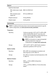
... Relative humidity Operating Storage Maximum vibration Operating Storage -40 °C to 65 °C (-40 °F to 500 Hz for specific system configurations, see support.dell.com/manuals. Physical Depth (includes bezel) With cabled power supply 660.2 mm (25.99 inch) unit With redundant power supply unit 677.3 mm (26.66 inch) Weight... temperature at 10 Hz to 149 °F) with 26 °C max dew point. NOTE: For information on supported expanded operating temperature range and configurations, see dell.com/environmental_datasheets.
... Relative humidity Operating Storage Maximum vibration Operating Storage -40 °C to 65 °C (-40 °F to 500 Hz for specific system configurations, see support.dell.com/manuals. Physical Depth (includes bezel) With cabled power supply 660.2 mm (25.99 inch) unit With redundant power supply unit 677.3 mm (26.66 inch) Weight... temperature at 10 Hz to 149 °F) with 26 °C max dew point. NOTE: For information on supported expanded operating temperature range and configurations, see dell.com/environmental_datasheets.

Owner's Manual
Page 1
Dell PowerEdge R320 Systems Owner's Manual Regulatory Model: E18S Series Regulatory Type: E18S001
Dell PowerEdge R320 Systems Owner's Manual Regulatory Model: E18S Series Regulatory Type: E18S001
Owner's Manual
Page 19
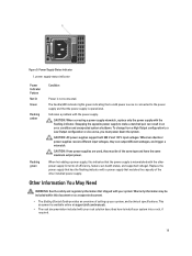
This document is available online at support.dell.com/manuals. • The rack documentation included with the flashing indicator. Power Supply Status Indicator 1. The handle/LED indicator lights green indicating that shipped with the power ...
This document is available online at support.dell.com/manuals. • The rack documentation included with the flashing indicator. Power Supply Status Indicator 1. The handle/LED indicator lights green indicating that shipped with the power ...

Owner's Manual
Page 20
• Any media that ships with your system that you purchased with your system, including those pertaining to the operating system, system management software, system updates, and system components that provides documentation and tools for updates on support.dell.com/manuals and read the updates first because they often supersede information in this document, see the Glossary at support.dell.com/ manuals. NOTE: Always check for configuring and managing your system. • For the full name of an abbreviation or acronym used in other documents. 20
• Any media that ships with your system that you purchased with your system, including those pertaining to the operating system, system management software, system updates, and system components that provides documentation and tools for updates on support.dell.com/manuals and read the updates first because they often supersede information in this document, see the Glossary at support.dell.com/ manuals. NOTE: Always check for configuring and managing your system. • For the full name of an abbreviation or acronym used in other documents. 20

Owner's Manual
Page 34
... For more information on or restart the managed system. 2. Turn on using iDRAC, see the Lifecycle Controller documentation at support.dell.com/manuals. For more information about setting up the Lifecycle Controller, configuring hardware and firmware, and deploying the operating system, see the ...iDRAC7 User's Guide under Software → Systems Management → Dell Remote Access Controllers, at support.dell.com/manuals. Press during the boot sequence and can enable or disable various iDRAC parameters using UEFI. In the System Setup...
... For more information on or restart the managed system. 2. Turn on using iDRAC, see the Lifecycle Controller documentation at support.dell.com/manuals. For more information about setting up the Lifecycle Controller, configuring hardware and firmware, and deploying the operating system, see the ...iDRAC7 User's Guide under Software → Systems Management → Dell Remote Access Controllers, at support.dell.com/manuals. Press during the boot sequence and can enable or disable various iDRAC parameters using UEFI. In the System Setup...
Owner's Manual
Page 68
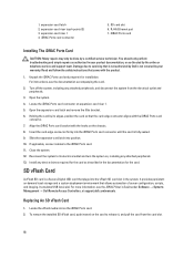
...see the documentation accompanying the card. 2. For instructions, see the iDRAC7 User's Guide under Software → Systems Management → Dell Remote Access Controllers, at support.dell.com/manuals. Damage due to the iDRAC Ports card. 11. Open the expansion-card latch and remove the filler bracket. 6. Holding the ... by its electrical outlet and turn the system on the card to its edges, position the card so that is not authorized by Dell is fully seated. 9. It provides persistent on the chassis. 8. It emulates USB device(s). Insert the card-edge connector firmly into ...
...see the documentation accompanying the card. 2. For instructions, see the iDRAC7 User's Guide under Software → Systems Management → Dell Remote Access Controllers, at support.dell.com/manuals. Damage due to the iDRAC Ports card. 11. Open the expansion-card latch and remove the filler bracket. 6. Holding the ... by its electrical outlet and turn the system on the card to its edges, position the card so that is not authorized by Dell is fully seated. 9. It provides persistent on the chassis. 8. It emulates USB device(s). Insert the card-edge connector firmly into ...

Owner's Manual
Page 77
...is more information on . 1. For information about the cable management arm, see the iDRAC7 User's Guide under Software → Systems Management → Dell Remote Access Controllers , at a time in a system that is not authorized by a certified service technician. If the output voltage of the active ..., or as directed by the online or telephone service and support team. CAUTION: The system requires one power supply at support.dell.com/ manuals. Damage due to unlatch and lift the optional cable management arm if it from the power distribution board and clear the chassis....
...is more information on . 1. For information about the cable management arm, see the iDRAC7 User's Guide under Software → Systems Management → Dell Remote Access Controllers , at a time in a system that is not authorized by a certified service technician. If the output voltage of the active ..., or as directed by the online or telephone service and support team. CAUTION: The system requires one power supply at support.dell.com/ manuals. Damage due to unlatch and lift the optional cable management arm if it from the power distribution board and clear the chassis....

Owner's Manual
Page 99
...peripherals. 10. CAUTION: Take care not to damage the system identification button while placing the system board into the chassis till the connectors at support.dell.com/manuals. 99 Hold the system board by its electrical outlet and turn the system on the chassis. 4. Replace the following: a) internal dual SD ... board. Lower the system board into the chassis. 2. For more information, see the iDRAC7 User's Guide under Software → Systems Management → Dell Remote Access Controllers,at the back of the system board align with the slots on the rear wall of the chassis. 3.
...peripherals. 10. CAUTION: Take care not to damage the system identification button while placing the system board into the chassis till the connectors at support.dell.com/manuals. 99 Hold the system board by its electrical outlet and turn the system on the chassis. 4. Replace the following: a) internal dual SD ... board. Lower the system board into the chassis. 2. For more information, see the iDRAC7 User's Guide under Software → Systems Management → Dell Remote Access Controllers,at the back of the system board align with the slots on the rear wall of the chassis. 3.

Owner's Manual
Page 111
... results • Run thorough tests to introduce additional test options to provide extra information about using diagnostics, see the Dell Online PowerEdge Diagnostics User's Guide under Software → Serviceability Tools, at support.dell.com/manuals. For information about the failed device(s) • View status messages that inform you to: • Run tests automatically or...
... results • Run thorough tests to introduce additional test options to provide extra information about using diagnostics, see the Dell Online PowerEdge Diagnostics User's Guide under Software → Serviceability Tools, at support.dell.com/manuals. For information about the failed device(s) • View status messages that inform you to: • Run tests automatically or...

Owner's Manual
Page 112
... the current overview of all tests run on all devices detected in the system. This is displayed if at support.dell.com/manuals. 112 For information about embedded system diagnostics, see the Dell Enhanced Pre-boot System Assessment User Guide at least one event description is displayed, listing all the detected devices. Event...
... the current overview of all tests run on all devices detected in the system. This is displayed if at support.dell.com/manuals. 112 For information about embedded system diagnostics, see the Dell Enhanced Pre-boot System Assessment User Guide at least one event description is displayed, listing all the detected devices. Event...

Owner's Manual
Page 117
... SSD, or Nearline SAS hard drives NOTE: Four hard-drive systems support software RAID. For more information on software RAID, see the Dell PowerEdge RAID Controller (PERC) documentation at support.dell.com/manuals. 117 7 Technical Specifications Processor Processor type Expansion Bus Bus type Expansion slots using riser card: Riser 1 Riser 2 Memory Architecture Memory module...
... SSD, or Nearline SAS hard drives NOTE: Four hard-drive systems support software RAID. For more information on software RAID, see the Dell PowerEdge RAID Controller (PERC) documentation at support.dell.com/manuals. 117 7 Technical Specifications Processor Processor type Expansion Bus Bus type Expansion slots using riser card: Riser 1 Riser 2 Memory Architecture Memory module...

Owner's Manual
Page 130
... Getting Help. 130 LCD Message An under voltage fault detected on PSU . Error Code Message Information LCD Message Details Action Power supply is in this manual. Details This failure may be of an electrical issue with cables or subsystem components in the system. Check PSU.
... Getting Help. 130 LCD Message An under voltage fault detected on PSU . Error Code Message Information LCD Message Details Action Power supply is in this manual. Details This failure may be of an electrical issue with cables or subsystem components in the system. Check PSU.

Owner's Manual
Page 131
... normal operations. Action Check input power. Review system configuration and power consumption. Check for power supply failures. Action Install matched power supplies and review this manual for watts. PSU1204 Message The power supplies are not redundant. Insufficient resources to operate in the system for damage. 3. Action 1. PSU1201 Message Power supply redundancy...
... normal operations. Action Check input power. Review system configuration and power consumption. Check for power supply failures. Action Install matched power supplies and review this manual for watts. PSU1204 Message The power supplies are not redundant. Insufficient resources to operate in the system for damage. 3. Action 1. PSU1201 Message Power supply redundancy...

Technical Guide
Page 11
... Figure 2 shows the optional locking bezel on the front of the R320 including USB connectors, Ethernet connectors, serial connector, video connector, PCIe slots, power supplies, and many other components and features described in this guide. For additional system views and features, see the Dell PowerEdge R320 Systems Owner's Manual on the back panel of the...
... Figure 2 shows the optional locking bezel on the front of the R320 including USB connectors, Ethernet connectors, serial connector, video connector, PCIe slots, power supplies, and many other components and features described in this guide. For additional system views and features, see the Dell PowerEdge R320 Systems Owner's Manual on the back panel of the...

Technical Guide
Page 12
... LED Front bezel Covers the system's front- loading hard drives and locks for security NMI button Used to the server 12 PowerEdge R320 Technical Guide For additional information, see the Dell PowerEdge R320 Systems Owner's Manual on the back and front of a system to help identify the unit in a data center environment Hard drives Up to...
... LED Front bezel Covers the system's front- loading hard drives and locks for security NMI button Used to the server 12 PowerEdge R320 Technical Guide For additional information, see the Dell PowerEdge R320 Systems Owner's Manual on the back and front of a system to help identify the unit in a data center environment Hard drives Up to...

Technical Guide
Page 13
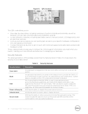
... on the front of the chassis as shown in Figure 5. Use your smartphone to access the Dell QRL app to learn more information about the server. 13 PowerEdge R320 Technical Guide a model- specific Quick Response (QR) code that is the Quick Resource Locator (QRL... navigation buttons to scroll through the menu on Support.Dell.com/Manuals. LCD control panel Quick Resource Locator A useful feature included with Dell PowerEdge 12th generation servers is located inside the R320 chassis cover (see the Dell PowerEdge R320 Systems Owner's Manual on the LCD and one select button Optional slim ...
... on the front of the chassis as shown in Figure 5. Use your smartphone to access the Dell QRL app to learn more information about the server. 13 PowerEdge R320 Technical Guide a model- specific Quick Response (QR) code that is the Quick Resource Locator (QRL... navigation buttons to scroll through the menu on Support.Dell.com/Manuals. LCD control panel Quick Resource Locator A useful feature included with Dell PowerEdge 12th generation servers is located inside the R320 chassis cover (see the Dell PowerEdge R320 Systems Owner's Manual on the LCD and one select button Optional slim ...
Technical Guide
Page 14
...task- TPM can quickly gain access to detect chassis intrusion. An internal switch is supported. TPM 1.2 is used to provide the Dell ID. BIOS has the ability to hard drives. QRL location This QRL code allows you more efficient and effective in Windows Server ...center. oriented videos and installation wizards • Locate reference materials, including searchable owner's manual content, LCD diagnostics, and an electrical overview • Look up a system password. 14 PowerEdge R320 Technical Guide No TPM version is integrated on the control panel or set up your service...
...task- TPM can quickly gain access to detect chassis intrusion. An internal switch is supported. TPM 1.2 is used to provide the Dell ID. BIOS has the ability to hard drives. QRL location This QRL code allows you more efficient and effective in Windows Server ...center. oriented videos and installation wizards • Locate reference materials, including searchable owner's manual content, LCD diagnostics, and an electrical overview • Look up a system password. 14 PowerEdge R320 Technical Guide No TPM version is integrated on the control panel or set up your service...
Technical Guide
Page 16
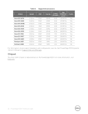
For more information, visit Intel.com. 16 PowerEdge R320 Technical Guide Chipset The Intel C600 chipset is implemented on Support.Dell.com/Manuals. Table 6. Supported processors Model Xeon E5-2470 Xeon E5-2440 Xeon E5-2430L Xeon E5-2430 Xeon E5-2420 Xeon E5-2450 Xeon E5-1410 .../s 1066MT/s 1066MT/s 1066MT/s 1066MT/s Turbo Yes Yes Yes Yes Yes Yes Yes NA NA NA NA For information on processor installation and configuration, see the Dell PowerEdge R320 Systems Owner's Manual on the PowerEdge R320.
For more information, visit Intel.com. 16 PowerEdge R320 Technical Guide Chipset The Intel C600 chipset is implemented on Support.Dell.com/Manuals. Table 6. Supported processors Model Xeon E5-2470 Xeon E5-2440 Xeon E5-2430L Xeon E5-2430 Xeon E5-2420 Xeon E5-2450 Xeon E5-1410 .../s 1066MT/s 1066MT/s 1066MT/s 1066MT/s Turbo Yes Yes Yes Yes Yes Yes Yes NA NA NA NA For information on processor installation and configuration, see the Dell PowerEdge R320 Systems Owner's Manual on the PowerEdge R320.

Technical Guide
Page 18
...followed by the SR DIMMs. For more information on memory configuration, see the Dell PowerEdge R320 Systems Owner's Manual on Support.Dell.com/Manuals. 18 PowerEdge R320 Technical Guide The system supports up to 2 DIMMs. The R320 supports a flexible memory configuration according to these basic rules: • Speed...For example, if DR DIMMS are supported on supported memory, visit Dell.com. For the latest information on the R320, ranging from the processor. • DIMMs should be placed in a system. The R320 has 3 memory channels per processor, with each channel, starting ...
...followed by the SR DIMMs. For more information on memory configuration, see the Dell PowerEdge R320 Systems Owner's Manual on Support.Dell.com/Manuals. 18 PowerEdge R320 Technical Guide The system supports up to 2 DIMMs. The R320 supports a flexible memory configuration according to these basic rules: • Speed...For example, if DR DIMMS are supported on supported memory, visit Dell.com. For the latest information on the R320, ranging from the processor. • DIMMs should be placed in a system. The R320 has 3 memory channels per processor, with each channel, starting ...

