
Getting Started Guide
Page 7
Securing the Power Cable Bend the system power cable as an uninterrupted power supply (UPS) or a power distribution unit (PDU). The power indicators should light. Plug the other end of the power cable into a grounded electrical outlet or a separate power source such as shown in the illustration and secure the cable in the retention clip. Turning On the System Press the power button on the system and the monitor. Getting Started With Your System 5
Securing the Power Cable Bend the system power cable as an uninterrupted power supply (UPS) or a power distribution unit (PDU). The power indicators should light. Plug the other end of the power cable into a grounded electrical outlet or a separate power source such as shown in the illustration and secure the cable in the retention clip. Turning On the System Press the power button on the system and the monitor. Getting Started With Your System 5

Getting Started Guide
Page 12
... connector 15-pin VGA Two 4-pin, USB 2.0-compliant Two 4-pin, USB 2.0-compliant Video Video type Video memory Matrox G200, integrated in Winbond WPCM450 8 MB Power AC power supply (per power supply) Wattage 250 W Voltage 100 VAC-240 VAC, 50 Hz/60 Hz, 4.0 A-2.0 A Heat dissipation 1040 BTU/hr maximum Maximum inrush current Under typical line conditions...
... connector 15-pin VGA Two 4-pin, USB 2.0-compliant Two 4-pin, USB 2.0-compliant Video Video type Video memory Matrox G200, integrated in Winbond WPCM450 8 MB Power AC power supply (per power supply) Wattage 250 W Voltage 100 VAC-240 VAC, 50 Hz/60 Hz, 4.0 A-2.0 A Heat dissipation 1040 BTU/hr maximum Maximum inrush current Under typical line conditions...
Owner's Manual
Page 7
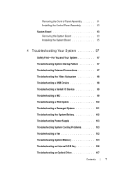
... Troubleshooting a USB Device 98 Troubleshooting a Serial I/O Device 99 Troubleshooting a NIC 99 Troubleshooting a Wet System 100 Troubleshooting a Damaged System 101 Troubleshooting the System Battery 102 Troubleshooting Power Supply 103 Troubleshooting System Cooling Problems 103 Troubleshooting a Fan 103 Troubleshooting System Memory 104 Troubleshooting an Internal USB Key 106 Troubleshooting an Optical Drive 107 Contents 7
... Troubleshooting a USB Device 98 Troubleshooting a Serial I/O Device 99 Troubleshooting a NIC 99 Troubleshooting a Wet System 100 Troubleshooting a Damaged System 101 Troubleshooting the System Battery 102 Troubleshooting Power Supply 103 Troubleshooting System Cooling Problems 103 Troubleshooting a Fan 103 Troubleshooting System Memory 104 Troubleshooting an Internal USB Key 106 Troubleshooting an Optical Drive 107 Contents 7
Owner's Manual
Page 12
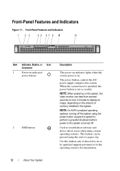
... to troubleshoot software and device driver errors when using the power button causes the system to perform a graceful shutdown before power to do so by qualified support personnel or by the operating system's documentation. 12 About Your System The power button controls the DC power supply output to display an image, depending on . Front-Panel...
... to troubleshoot software and device driver errors when using the power button causes the system to perform a graceful shutdown before power to do so by qualified support personnel or by the operating system's documentation. 12 About Your System The power button controls the DC power supply output to display an image, depending on . Front-Panel...

Owner's Manual
Page 15
Connects the optional system status indicator assembly through the optional cable management arm. 250 W power supply. See "Entering the System Setup Program" on the front and back panels light blue until one of the buttons is ..., Button, or Icon Connector 9 System status indicator 10 System identification button 11 System identification connector 12 Power supply 13 Retention clip Description Lights blue during normal system operation. Secures the power cable. About Your System 15 The system identification buttons on your system, use the System Setup program....
Connects the optional system status indicator assembly through the optional cable management arm. 250 W power supply. See "Entering the System Setup Program" on the front and back panels light blue until one of the buttons is ..., Button, or Icon Connector 9 System status indicator 10 System identification button 11 System identification connector 12 Power supply 13 Retention clip Description Lights blue during normal system operation. Secures the power cable. About Your System 15 The system identification buttons on your system, use the System Setup program....

Owner's Manual
Page 48
Figure 3-1. Inside the System 4 3 2 1 5 6 7 10 1 control panel board 3 power supply 5 heat sink/processor 7 expansion card 9 system cooling fans (3) 8 9 2 hard drives (2) 4 cooling shroud 6 expansion-card riser 8 chassis intrusion switch 10 optical drive 48 Installing System ... and simple repairs as directed by the online or telephone service and support team. Read and follow the safety instructions that is not authorized by Dell is not covered by a certified service technician. Inside the System CAUTION: Many repairs may only be done by your product documentation, or as ...
Figure 3-1. Inside the System 4 3 2 1 5 6 7 10 1 control panel board 3 power supply 5 heat sink/processor 7 expansion card 9 system cooling fans (3) 8 9 2 hard drives (2) 4 cooling shroud 6 expansion-card riser 8 chassis intrusion switch 10 optical drive 48 Installing System ... and simple repairs as directed by the online or telephone service and support team. Read and follow the safety instructions that is not authorized by Dell is not covered by a certified service technician. Inside the System CAUTION: Many repairs may only be done by your product documentation, or as ...
Owner's Manual
Page 87
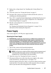
... the system board, hard drive(s), and optical drive. Removing the Power Supply CAUTION: Many repairs may have to servicing that came with power-supply removal. Read and follow the safety instructions that is not authorized by Dell is not covered by your product documentation, or as directed by... a certified service technician. Note the routing of the power cables as authorized in your warranty...
... the system board, hard drive(s), and optical drive. Removing the Power Supply CAUTION: Many repairs may have to servicing that came with power-supply removal. Read and follow the safety instructions that is not authorized by Dell is not covered by your product documentation, or as directed by... a certified service technician. Note the routing of the power cables as authorized in your warranty...

Owner's Manual
Page 88
See Figure 3-18. 5 Remove the screw securing the power supply to the chassis. 6 Slide and lift the power supply to remove it from the chassis. Figure 3-18. Removing and Installing the Power Supply 2 1 6 1 screw 3 24-pin power cable 5 optical drive cable 3 4 5 2 power supply 4 4-pin power cable 6 SATA power cables (2) 88 Installing System Components
See Figure 3-18. 5 Remove the screw securing the power supply to the chassis. 6 Slide and lift the power supply to remove it from the chassis. Figure 3-18. Removing and Installing the Power Supply 2 1 6 1 screw 3 24-pin power cable 5 optical drive cable 3 4 5 2 power supply 4 4-pin power cable 6 SATA power cables (2) 88 Installing System Components
Owner's Manual
Page 89
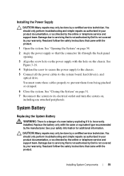
... follow the safety instructions that is not authorized by Dell is not covered by the online or telephone service and support team. You must route these cables properly to the system board, hard drive(s), and optical drive. Installing the Power Supply CAUTION: Many repairs may only be done by ... information for additional information. Damage due to servicing that the connector fits through the back-panel opening. 3 Align the screw hole on the power supply with the product. See "Closing the System" on page 51. 7 Reconnect the system to servicing that came with the hole on , ...
... follow the safety instructions that is not authorized by Dell is not covered by the online or telephone service and support team. You must route these cables properly to the system board, hard drive(s), and optical drive. Installing the Power Supply CAUTION: Many repairs may only be done by ... information for additional information. Damage due to servicing that the connector fits through the back-panel opening. 3 Align the screw hole on the power supply with the product. See "Closing the System" on page 51. 7 Reconnect the system to servicing that came with the hole on , ...
Owner's Manual
Page 93
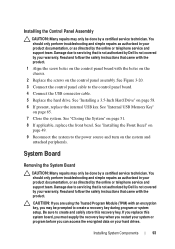
... you replace this recovery key. See Figure 3-20. 3 Connect the control panel cable to the power source and turn on your warranty. Read and follow the safety instructions that is not authorized by Dell is not covered by the online or telephone service and support team. Read and follow the safety... instructions that is not authorized by Dell is not covered by the online or telephone service and support team. Damage due to create and safely store this system board, you must supply the recovery key when you restart your system or program before you ...
... you replace this recovery key. See Figure 3-20. 3 Connect the control panel cable to the power source and turn on your warranty. Read and follow the safety instructions that is not authorized by Dell is not covered by the online or telephone service and support team. Read and follow the safety... instructions that is not authorized by Dell is not covered by the online or telephone service and support team. Damage due to create and safely store this system board, you must supply the recovery key when you restart your system or program before you ...
Owner's Manual
Page 101
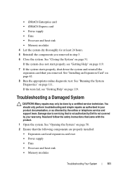
... on page 119. 7 If the system starts properly, shut down the system and reinstall the expansion card that is not authorized by Dell is not covered by the online or telephone service and support team. See "Running the System Diagnostics" on page 50. 2 Ensure ...service technician. Read and follow the safety instructions that the following components are properly installed: • Expansion card and expansion-card riser • Power supply • Fans • Processor and heat sink • Memory modules Troubleshooting Your System 101 See "Installing an Expansion Card" on page 51...
... on page 119. 7 If the system starts properly, shut down the system and reinstall the expansion card that is not authorized by Dell is not covered by the online or telephone service and support team. See "Running the System Diagnostics" on page 50. 2 Ensure ...service technician. Read and follow the safety instructions that the following components are properly installed: • Expansion card and expansion-card riser • Power supply • Fans • Processor and heat sink • Memory modules Troubleshooting Your System 101 See "Installing an Expansion Card" on page 51...

Owner's Manual
Page 103
... or has failed. Read and follow the safety instructions that is not authorized by Dell is functioning properly. 2 If the problem persists, replace the faulty power supply. Troubleshooting Power Supply 1 Reseat the power supply by removing and reinstalling it is working properly. The power indicator turns green to servicing that came with the product. Damage due to signify...
... or has failed. Read and follow the safety instructions that is not authorized by Dell is functioning properly. 2 If the problem persists, replace the faulty power supply. Troubleshooting Power Supply 1 Reseat the power supply by removing and reinstalling it is working properly. The power indicator turns green to servicing that came with the product. Damage due to signify...
Owner's Manual
Page 123
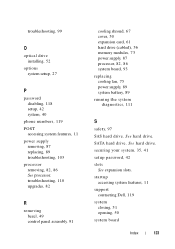
...board, 93 replacing cooling fan, 75 power supply, 89 system battery, 89 running the system diagnostics, 111 S safety, 97 SAS hard drive. See hard drive. See hard drive. SATA hard drive. startup accessing system features, 11 support contacting Dell, 119 system closing, 51 opening, 50... system board Index 123 troubleshooting, 99 O optical drive installing, 52 options system setup, 27 P password disabling, 118 setup, 42 system, 40 phone numbers, 119 POST accessing system features, 11 power supply removing, 87 replacing,...
...board, 93 replacing cooling fan, 75 power supply, 89 system battery, 89 running the system diagnostics, 111 S safety, 97 SAS hard drive. See hard drive. See hard drive. SATA hard drive. startup accessing system features, 11 support contacting Dell, 119 system closing, 51 opening, 50... system board Index 123 troubleshooting, 99 O optical drive installing, 52 options system setup, 27 P password disabling, 118 setup, 42 system, 40 phone numbers, 119 POST accessing system features, 11 power supply removing, 87 replacing,...
Owner's Manual
Page 124
..., 27 system setup program boot settings, 31 entering, 26 integrated devices options, 31 keystroke, 26 memory settings, 29 PCI IRQ assignments, 32 power management options, 34 processor settings, 29 SATA settings, 30 serial communications options, 33 system security options, 35 system setup screens main, 27 ... damaged system, 101 expansion card, 109 external connections, 97 hard drive, 108 internal USB key, 106 keyboard, 98 memory, 104 NIC, 99 power supply, 103 processor, 110 system cooling, 103 video, 98 wet system, 100 U UEFI Boot Manager entering, 37 main screen, 38 System Utilities screen...
..., 27 system setup program boot settings, 31 entering, 26 integrated devices options, 31 keystroke, 26 memory settings, 29 PCI IRQ assignments, 32 power management options, 34 processor settings, 29 SATA settings, 30 serial communications options, 33 system security options, 35 system setup screens main, 27 ... damaged system, 101 expansion card, 109 external connections, 97 hard drive, 108 internal USB key, 106 keyboard, 98 memory, 104 NIC, 99 power supply, 103 processor, 110 system cooling, 103 video, 98 wet system, 100 U UEFI Boot Manager entering, 37 main screen, 38 System Utilities screen...


