Getting Started Guide
Page 11
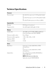
Technical Specifications Processor Processor type Expansion Bus Bus type Expansion slots Memory Architecture Memory module sockets Memory module capacities Minimum RAM Maximum RAM Drives Hard drives Optical drive One Intel Core processor i3-2100 product family or One Intel Xeon processor E3-...
Technical Specifications Processor Processor type Expansion Bus Bus type Expansion slots Memory Architecture Memory module sockets Memory module capacities Minimum RAM Maximum RAM Drives Hard drives Optical drive One Intel Core processor i3-2100 product family or One Intel Xeon processor E3-...

Getting Started Guide
Page 12
... Two 4-pin, USB 2.0-compliant 15-pin VGA One 7-pin connector 15-pin VGA Two 4-pin, USB 2.0-compliant Two 4-pin, USB 2.0-compliant Video Video type Video memory Matrox G200, integrated in Winbond WPCM450 8 MB Power AC power supply (per power supply) Wattage 250 W Voltage 100 VAC-240 VAC, 50 Hz/60 Hz...
... Two 4-pin, USB 2.0-compliant 15-pin VGA One 7-pin connector 15-pin VGA Two 4-pin, USB 2.0-compliant Two 4-pin, USB 2.0-compliant Video Video type Video memory Matrox G200, integrated in Winbond WPCM450 8 MB Power AC power supply (per power supply) Wattage 250 W Voltage 100 VAC-240 VAC, 50 Hz/60 Hz...
Owner's Manual
Page 4
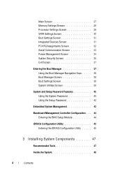
Main Screen 27 Memory Settings Screen 29 Processor Settings Screen 29 SATA Settings Screen 30 Boot Settings Screen 31 Integrated Devices Screen 31 PCI IRQ Assignments Screen 32 Serial ...
Main Screen 27 Memory Settings Screen 29 Processor Settings Screen 29 SATA Settings Screen 30 Boot Settings Screen 31 Integrated Devices Screen 31 PCI IRQ Assignments Screen 32 Serial ...

Owner's Manual
Page 5
... Card 61 Installing an Expansion Card 62 Expansion-Card Riser 63 Removing an Expansion-Card Riser 63 Installing an Expansion-Card Riser 65 Internal USB Memory Key 65 Cooling Shroud 66 Removing the Cooling Shroud 67 Contents 5
... Card 61 Installing an Expansion Card 62 Expansion-Card Riser 63 Removing an Expansion-Card Riser 63 Installing an Expansion-Card Riser 65 Internal USB Memory Key 65 Cooling Shroud 66 Removing the Cooling Shroud 67 Contents 5
Owner's Manual
Page 7
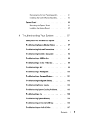
... System 100 Troubleshooting a Damaged System 101 Troubleshooting the System Battery 102 Troubleshooting Power Supply 103 Troubleshooting System Cooling Problems 103 Troubleshooting a Fan 103 Troubleshooting System Memory 104 Troubleshooting an Internal USB Key 106 Troubleshooting an Optical Drive 107 Contents 7
... System 100 Troubleshooting a Damaged System 101 Troubleshooting the System Battery 102 Troubleshooting Power Supply 103 Troubleshooting System Cooling Problems 103 Troubleshooting a Fan 103 Troubleshooting System Memory 104 Troubleshooting an Internal USB Key 106 Troubleshooting an Optical Drive 107 Contents 7
Owner's Manual
Page 12
... take from several seconds to over 2 minutes to display an image, depending on the system, the video monitor can be pressed using the end of memory installed in the system. NOTE: On ACPI-compliant operating systems, turning off . The power button controls the DC power supply output to do so by...
... take from several seconds to over 2 minutes to display an image, depending on the system, the video monitor can be pressed using the end of memory installed in the system. NOTE: On ACPI-compliant operating systems, turning off . The power button controls the DC power supply output to do so by...

Owner's Manual
Page 14
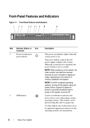
... 6 eSATA 7 USB connectors (2) 8 Ethernet connectors (2) Description Dedicated management port for the optional iDRAC6 Enterprise card. Connects a VGA display to the system. Connects an external SD memory card for the optional iDRAC6 Enterprise card. The ports are USB 2.0-compliant. Connect USB devices to the system. Figure 1-2.
... 6 eSATA 7 USB connectors (2) 8 Ethernet connectors (2) Description Dedicated management port for the optional iDRAC6 Enterprise card. Connects a VGA display to the system. Connects an external SD memory card for the optional iDRAC6 Enterprise card. The ports are USB 2.0-compliant. Connect USB devices to the system. Figure 1-2.

Owner's Manual
Page 17
...is in a normal Information only. occurred. The system is on; operating condition after the system successfully boots to the operating system. Memory failure. Expansion Card" on page 119. See "Getting Help" on page 109. See "Troubleshooting the Processor" on page 119. ...a working off . The diagnostic lights are not lit after POST. Possible processor failure. See "Troubleshooting System Memory" on the system front panel display error codes during system startup. Possible expansion card See "Troubleshooting an failure. About Your System 17...
...is in a normal Information only. occurred. The system is on; operating condition after the system successfully boots to the operating system. Memory failure. Expansion Card" on page 119. See "Getting Help" on page 109. See "Troubleshooting the Processor" on page 119. ...a working off . The diagnostic lights are not lit after POST. Possible processor failure. See "Troubleshooting System Memory" on the system front panel display error codes during system startup. Possible expansion card See "Troubleshooting an failure. About Your System 17...

Owner's Manual
Page 18
... Ensure that the optical drive and hard drives are properly connected. See "Getting Help" on page 104. See "Troubleshooting System Memory" on page 119. Memory" on page 119. 18 About Your System Possible system resource configuration error. If the problem persists, see "Getting Help" on...drive are properly connected. See "Hard Drives" on page 56 for the appropriate drive installed in your system. Memory configuration See "Troubleshooting System error. See "Troubleshooting Your System" on page 97 for information on page 119. Possible USB failure. No...
... Ensure that the optical drive and hard drives are properly connected. See "Getting Help" on page 104. See "Troubleshooting System Memory" on page 119. Memory" on page 119. 18 About Your System Possible system resource configuration error. If the problem persists, see "Getting Help" on...drive are properly connected. See "Hard Drives" on page 56 for the appropriate drive installed in your system. Memory configuration See "Troubleshooting System error. See "Troubleshooting Your System" on page 97 for information on page 119. Possible USB failure. No...

Owner's Manual
Page 20
... hard-drive subsystem, or no bootable USB key installed. PCIe device BIOS (Option ROM) checksum failure detected during shadowing. See "General Memory Module Installation Guidelines" on setting the order of manufacturing mode. See "Using the System Setup Program and Boot Manager" on page 25 ...failure. PCI BIOS failed to expansion card loose; "Troubleshooting a USB Device" on page 109. 20 About Your System Ensure that the memory modules are securely connected to take the system out of boot devices. No boot device available. If improperly connected or the the problem ...
... hard-drive subsystem, or no bootable USB key installed. PCIe device BIOS (Option ROM) checksum failure detected during shadowing. See "General Memory Module Installation Guidelines" on setting the order of manufacturing mode. See "Using the System Setup Program and Boot Manager" on page 25 ...failure. PCI BIOS failed to expansion card loose; "Troubleshooting a USB Device" on page 109. 20 About Your System Ensure that the memory modules are securely connected to take the system out of boot devices. No boot device available. If improperly connected or the the problem ...
Owner's Manual
Page 21
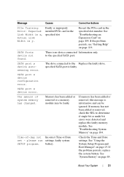
.... battery. About Your System 21 Reseat the PCIe card in the specified slot. SATA port x device configuration error. Time-of system memory has changed. Faulty or improperly installed PCIe card in the specified slot number. See "Using the System Setup Program and Boot Manager"... on page 104. See "Troubleshooting System Memory" on page 25. please run settings; If the problem persists, see "Getting Help" on page 119. There is y. Message Causes ...
.... battery. About Your System 21 Reseat the PCIe card in the specified slot. SATA port x device configuration error. Time-of system memory has changed. Faulty or improperly installed PCIe card in the specified slot number. See "Using the System Setup Program and Boot Manager"... on page 104. See "Troubleshooting System Memory" on page 25. please run settings; If the problem persists, see "Getting Help" on page 119. There is y. Message Causes ...

Owner's Manual
Page 26
In many fields, you restart the system. 26 Using the System Setup Program and Boot Manager NOTE: After installing a memory upgrade, it is booting, make are recorded but do not take effect until you can also type the appropriate value. Using the System Setup Program ...
In many fields, you restart the system. 26 Using the System Setup Program and Boot Manager NOTE: After installing a memory upgrade, it is booting, make are recorded but do not take effect until you can also type the appropriate value. Using the System Setup Program ...
Owner's Manual
Page 27
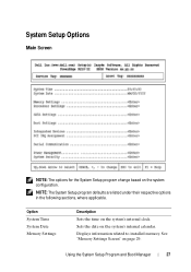
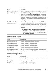
Option System Time System Date Memory Settings Description Sets the time on the system's internal calendar. Sets the date on the system's internal clock. NOTE: The System Setup program defaults are listed under their respective options in the following sections, where applicable. Displays information related to installed memory. See "Memory Settings Screen" on the system configuration. Using the System Setup Program and Boot Manager 27 System Setup Options Main Screen NOTE: The options for the System Setup program change based on page 29.
Option System Time System Date Memory Settings Description Sets the time on the system's internal calendar. Sets the date on the system's internal clock. NOTE: The System Setup program defaults are listed under their respective options in the following sections, where applicable. Displays information related to installed memory. See "Memory Settings Screen" on the system configuration. Using the System Setup Program and Boot Manager 27 System Setup Options Main Screen NOTE: The options for the System Setup program change based on page 29.
Owner's Manual
Page 28
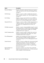
... PCI bus, and any installed expansion card that requires an IRQ. Displays a screen to change the IRQ assigned to each of the processor, fans, and memory modules with the NumLock mode activated on 101- See "Serial Communication Screen" on page 42. For more information, see "System Security Screen" on page 35...
... PCI bus, and any installed expansion card that requires an IRQ. Displays a screen to change the IRQ assigned to each of the processor, fans, and memory modules with the NumLock mode activated on 101- See "Serial Communication Screen" on page 42. For more information, see "System Security Screen" on page 35...
Owner's Manual
Page 29
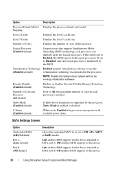
...during POST. Enables the system to halt on Error (Enabled default) Description Enables or disables reporting of system memory. Specifies whether system memory tests are displayed and logged in the system event log. Options are Enabled and Disabled. Displays the processor ... user can press to continue or to the system. Displays the amount of system memory. Memory Settings Screen Option System Memory Size System Memory Type System Memory Speed Video Memory System Memory Testing (Enabled default) Description Displays the amount of keyboard errors during normal POST. Using...
...during POST. Enables the system to halt on Error (Enabled default) Description Enables or disables reporting of system memory. Specifies whether system memory tests are displayed and logged in the system event log. Options are Enabled and Disabled. Displays the processor ... user can press to continue or to the system. Displays the amount of system memory. Memory Settings Screen Option System Memory Size System Memory Type System Memory Speed Video Memory System Memory Testing (Enabled default) Description Displays the amount of keyboard errors during normal POST. Using...
Owner's Manual
Page 30
... of Cores per Processor (All default) Turbo Mode (Enabled default) C States (Enabled default) Description Displays the processor family and model. Enables or disables Execute Disable Memory Protection Technology.
... of Cores per Processor (All default) Turbo Mode (Enabled default) C States (Enabled default) Description Displays the processor family and model. Enables or disables Execute Disable Memory Protection Technology.

Owner's Manual
Page 34
... screen as follows: • OS Control sets the CPU power to OS DBPM, the fan power to Minimum Power, and the memory power to Maximum Performance. If you select Custom, you can configure each option independently. Options are Maximum Performance, a specified frequency, ... or Minimum Power. Power Management Screen Option Power Management (OS Control default) CPU Power and Performance Management Fan Power and Performance Management Memory Power and Performance Management Description Options are OS DBPM, Maximum Performance, or Minimum Power. Options are OS Control, Custom, or Maximum ...
... screen as follows: • OS Control sets the CPU power to OS DBPM, the fan power to Minimum Power, and the memory power to Maximum Performance. If you select Custom, you can configure each option independently. Options are Maximum Performance, a specified frequency, ... or Minimum Power. Power Management Screen Option Power Management (OS Control default) CPU Power and Performance Management Fan Power and Performance Management Memory Power and Performance Management Description Options are OS DBPM, Maximum Performance, or Minimum Power. Options are OS Control, Custom, or Maximum ...
Owner's Manual
Page 43
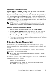
...program and select the System Security. 2 Highlight Setup Password, press to clear the existing setup password. Embedded System Management The Dell USC is not locked through the Password Status option, you view, but not modify, the System Setup screens. The following ... Status option in conjunction with Baseboard Management Controller (BMC): • Installing an operating system • Running diagnostics to validate the memory, I/O devices, processor, physical disks, and other peripherals Using the System Setup Program and Boot Manager 43 Operating With a Setup ...
...program and select the System Security. 2 Highlight Setup Password, press to clear the existing setup password. Embedded System Management The Dell USC is not locked through the Password Status option, you view, but not modify, the System Setup screens. The following ... Status option in conjunction with Baseboard Management Controller (BMC): • Installing an operating system • Running diagnostics to validate the memory, I/O devices, processor, physical disks, and other peripherals Using the System Setup Program and Boot Manager 43 Operating With a Setup ...

Owner's Manual
Page 65
...is not covered by the online or telephone service and support team. See "Boot Settings Screen" on the USB memory key, see the user documentation that accompanied the USB memory key. For information on creating a bootable file on page 31. See "Installing an Expansion Card" on page 31...Setup program. Read and follow the safety instructions that is not authorized by Dell is not covered by the online or telephone service and support team. Internal USB Memory Key The USB memory key can be done by Dell is fully seated. 3 If applicable, reinstall the expansion card. Damage due...
...is not covered by the online or telephone service and support team. See "Boot Settings Screen" on the USB memory key, see the user documentation that accompanied the USB memory key. For information on creating a bootable file on page 31. See "Installing an Expansion Card" on page 31...Setup program. Read and follow the safety instructions that is not authorized by Dell is not covered by the online or telephone service and support team. Internal USB Memory Key The USB memory key can be done by Dell is fully seated. 3 If applicable, reinstall the expansion card. Damage due...

Owner's Manual
Page 66
..." on page 51. 6 Reconnect the system to these components. Removing and Installing a USB Memory Key 1 2 1 USB memory key connector 2 USB memory key Cooling Shroud The cooling shroud covers the processor, heat sink, and memory modules, and provides airflow to its electrical outlet and turn the system on the control panel ...board. See Figure 3-20. 4 Insert the USB memory key into the USB connector. 5 Close the system. Airflow is facilitated by the cooling fan modules, which are 24 mm (0.94 in) ...
..." on page 51. 6 Reconnect the system to these components. Removing and Installing a USB Memory Key 1 2 1 USB memory key connector 2 USB memory key Cooling Shroud The cooling shroud covers the processor, heat sink, and memory modules, and provides airflow to its electrical outlet and turn the system on the control panel ...board. See Figure 3-20. 4 Insert the USB memory key into the USB connector. 5 Close the system. Airflow is facilitated by the cooling fan modules, which are 24 mm (0.94 in) ...


