Getting Started Guide
Page 11
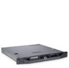
Technical Specifications Processor Processor type Expansion Bus Bus type Expansion slots Memory Architecture Memory module sockets Memory module capacities Minimum RAM Maximum RAM Drives Hard drives Optical drive One Intel Core processor i3-2100 product family ...
Technical Specifications Processor Processor type Expansion Bus Bus type Expansion slots Memory Architecture Memory module sockets Memory module capacities Minimum RAM Maximum RAM Drives Hard drives Optical drive One Intel Core processor i3-2100 product family ...

Owner's Manual
Page 14
Figure 1-2. Connects a serial device to the system. Connects a PCI Express expansion card. Embedded 10/100/1000 NIC connectors. 14 About Your System The ports are USB 2.0-compliant. ...and Indicators 1 2 3 4 5 6 7 8 9 10 11 12 13 Item Indicator, Button, or Icon Connector 1 iDRAC6 Enterprise port (optional) 2 VFlash media slot (optional) 3 PCIe expansion card slot 4 Serial connector 5 Video connector 6 eSATA 7 USB connectors (2) 8 Ethernet connectors (2) Description Dedicated management port for the optional iDRAC6 Enterprise card. Connects a VGA display...
Figure 1-2. Connects a serial device to the system. Connects a PCI Express expansion card. Embedded 10/100/1000 NIC connectors. 14 About Your System The ports are USB 2.0-compliant. ...and Indicators 1 2 3 4 5 6 7 8 9 10 11 12 13 Item Indicator, Button, or Icon Connector 1 iDRAC6 Enterprise port (optional) 2 VFlash media slot (optional) 3 PCIe expansion card slot 4 Serial connector 5 Video connector 6 eSATA 7 USB connectors (2) 8 Ethernet connectors (2) Description Dedicated management port for the optional iDRAC6 Enterprise card. Connects a VGA display...
Owner's Manual
Page 21
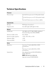
...faulty system SETUP program. See "System Battery" on page 104. Reseat the PCIe card in the specified slot. SATA Portx device not found. There is informative and can be faulty. SATA port x device configuration error...Training Error: Expected Link Width is x, Actual Link Width is faulty. Faulty or improperly installed PCIe card in the specified slot number. to the Replace the faulty drive. If memory has not been added or removed, check the SEL to determine ... module. The amount of -day not Incorrect Time or Date set - See "Troubleshooting an Expansion Card" on page 109.
...faulty system SETUP program. See "System Battery" on page 104. Reseat the PCIe card in the specified slot. SATA Portx device not found. There is informative and can be faulty. SATA port x device configuration error...Training Error: Expected Link Width is x, Actual Link Width is faulty. Faulty or improperly installed PCIe card in the specified slot number. to the Replace the faulty drive. If memory has not been added or removed, check the SEL to determine ... module. The amount of -day not Incorrect Time or Date set - See "Troubleshooting an Expansion Card" on page 109.
Owner's Manual
Page 58
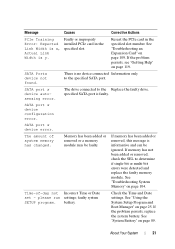
Read and follow the safety instructions that is not authorized by Dell is not covered by your product documentation, or as directed by a certified service technician....hard drives), connect the data cable to servicing that came with the four tabs on page 60. 5 Align the four slots under the hard-drive carrier with the product. 1 Turn off the system and attached peripherals, and disconnect the system .... See Figure 3-7. For information on installing a SAS controller card, see "Installing an Expansion Card" on the card edge. Damage due to the connector on page 62. 7 Close the system.
Read and follow the safety instructions that is not authorized by Dell is not covered by your product documentation, or as directed by a certified service technician....hard drives), connect the data cable to servicing that came with the four tabs on page 60. 5 Align the four slots under the hard-drive carrier with the product. 1 Turn off the system and attached peripherals, and disconnect the system .... See Figure 3-7. For information on installing a SAS controller card, see "Installing an Expansion Card" on the card edge. Damage due to the connector on page 62. 7 Close the system.

Owner's Manual
Page 61
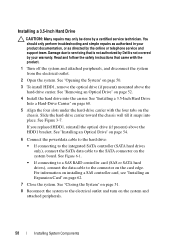
... a metal filler bracket over the empty expansion-card slot opening and close the expansion-card latch. Installing System Components 61 Damage due to servicing that came with the product. 1 Turn off the system, including any attached peripherals. Read and follow the safety instructions that is not authorized by Dell is not hot-swappable. See...
... a metal filler bracket over the empty expansion-card slot opening and close the expansion-card latch. Installing System Components 61 Damage due to servicing that came with the product. 1 Turn off the system, including any attached peripherals. Read and follow the safety instructions that is not authorized by Dell is not hot-swappable. See...

Owner's Manual
Page 64
.... support team. Damage due to servicing that came with the product. 1 Turn off the system, including any attached peripherals, and disconnect the system from the expansion slot. Read and follow the safety instructions that is not authorized by Dell is not covered by your warranty. See Figure 3-9.
.... support team. Damage due to servicing that came with the product. 1 Turn off the system, including any attached peripherals, and disconnect the system from the expansion slot. Read and follow the safety instructions that is not authorized by Dell is not covered by your warranty. See Figure 3-9.

Owner's Manual
Page 76
...tab snaps over the edge of the holder. 76 Installing System Components See "Opening the System" on page 50. 3 If installed, remove the expansion card from the electrical outlet. 2 Open the system. See "Installing the Cooling Shroud" on the system board. See "Removing an... Expansion Card" on page 61. 4 Insert the tab on the Integrated Dell Remote Access Controller 6 (iDRAC6) Express card into the clip on , including any attached peripherals, and disconnect the system from the expansion-card slot. See Figure 3-14. When the front of the ...
...tab snaps over the edge of the holder. 76 Installing System Components See "Opening the System" on page 50. 3 If installed, remove the expansion card from the electrical outlet. 2 Open the system. See "Installing the Cooling Shroud" on the system board. See "Removing an... Expansion Card" on page 61. 4 Insert the tab on the Integrated Dell Remote Access Controller 6 (iDRAC6) Express card into the clip on , including any attached peripherals, and disconnect the system from the expansion-card slot. See Figure 3-14. When the front of the ...

Owner's Manual
Page 78
...that is not authorized by Dell is not covered by your product documentation, or as authorized in your warranty. See "Removing an Expansion Card" on page 61... from the electrical outlet. 2 Open the system. See "Installing an Expansion Card" on the retention standoff tab at the front edge of the ... the System" on the system board. 6 If applicable, reinstall the expansion card. You should only perform troubleshooting and simple repairs as directed by...slips through the clip on page 50. 3 If installed, remove the expansion card from the system board connector. 5 Angle the card so that ...
...that is not authorized by Dell is not covered by your product documentation, or as authorized in your warranty. See "Removing an Expansion Card" on page 61... from the electrical outlet. 2 Open the system. See "Installing an Expansion Card" on the retention standoff tab at the front edge of the ... the System" on the system board. 6 If applicable, reinstall the expansion card. You should only perform troubleshooting and simple repairs as directed by...slips through the clip on page 50. 3 If installed, remove the expansion card from the system board connector. 5 Angle the card so that ...
Owner's Manual
Page 79
...and simple repairs as directed by Dell is fully seated, the plastic standoffs snap over the edge of the card with the product. 1 Turn off the system, including any attached peripherals, and disconnect the system from the expansion slot. See "Removing an Expansion Card" on page 50. 3... If installed, remove the expansion card from the electrical outlet. 2 Open the system. See Figure 3-15. Installing System Components 79 ...
...and simple repairs as directed by Dell is fully seated, the plastic standoffs snap over the edge of the card with the product. 1 Turn off the system, including any attached peripherals, and disconnect the system from the expansion slot. See "Removing an Expansion Card" on page 50. 3... If installed, remove the expansion card from the electrical outlet. 2 Open the system. See Figure 3-15. Installing System Components 79 ...

Owner's Manual
Page 80
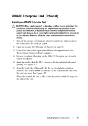
Removing and Installing an iDRAC6 Enterprise Card 2 3 1 4 6 5 1 iDRAC6 Enterprise card 3 VFlash SD card 5 retention standoff tabs (2) 2 VFlash media slot 4 retention standoff posts (2) 6 iDRAC6 Enterprise card connector 7 If applicable, reinstall the expansion card. Figure 3-15. See "Installing an Expansion Card" on , including any attached peripherals. 80 Installing System Components See "Closing the System" on page 51. 9 Reconnect the system to its electrical outlet and turn the system on page 62. 8 Close the system.
Removing and Installing an iDRAC6 Enterprise Card 2 3 1 4 6 5 1 iDRAC6 Enterprise card 3 VFlash SD card 5 retention standoff tabs (2) 2 VFlash media slot 4 retention standoff posts (2) 6 iDRAC6 Enterprise card connector 7 If applicable, reinstall the expansion card. Figure 3-15. See "Installing an Expansion Card" on , including any attached peripherals. 80 Installing System Components See "Closing the System" on page 51. 9 Reconnect the system to its electrical outlet and turn the system on page 62. 8 Close the system.
Owner's Manual
Page 81
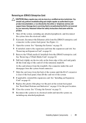
...connector is not covered by Dell is clear of the back panel, then lift the card out of the retention standoffs. Read and follow the safety instructions that is not authorized by your product documentation, or as authorized in your warranty. See "Removing an Expansion Card" on the two ... See "Removing a VFlash Media Card" on page 82. 6 Pull back slightly on page 61. 5 Remove the VFlash media (if installed) from the expansion-card slot. Damage due to its electrical outlet and turn the system on page 14 for the port location. 10 Close the system. Removing an iDRAC6 Enterprise...
...connector is not covered by Dell is clear of the back panel, then lift the card out of the retention standoffs. Read and follow the safety instructions that is not authorized by your product documentation, or as authorized in your warranty. See "Removing an Expansion Card" on the two ... See "Removing a VFlash Media Card" on page 82. 6 Pull back slightly on page 61. 5 Remove the VFlash media (if installed) from the expansion-card slot. Damage due to its electrical outlet and turn the system on page 14 for the port location. 10 Close the system. Removing an iDRAC6 Enterprise...
Owner's Manual
Page 121
... installing, 62 removing, 61 troubleshooting, 109 expansion slot, 61 Index 121 Index B back-panel features and indicators, 14 battery (system) replacing, 89 bezel, 49 BMC configuring, 44 C cabling optical drive, 52 CD drive troubleshooting, 107 CD/DVD drive See optical drive. chassis intrusion switch, 48 contacting Dell, 119 control panel assembly installing, 93...
... installing, 62 removing, 61 troubleshooting, 109 expansion slot, 61 Index 121 Index B back-panel features and indicators, 14 battery (system) replacing, 89 bezel, 49 BMC configuring, 44 C cabling optical drive, 52 CD drive troubleshooting, 107 CD/DVD drive See optical drive. chassis intrusion switch, 48 contacting Dell, 119 control panel assembly installing, 93...
Owner's Manual
Page 123
... features, 11 support contacting Dell, 119 system closing, 51 opening, 50 system board Index 123 See hard drive. See hard drive. SATA hard drive. troubleshooting, 110 upgrades, 82 R removing bezel, 49 control panel assembly, 91 cooling shroud, 67 cover, 50 expansion card, 61 hard drive ... system battery, 89 running the system diagnostics, 111 S safety, 97 SAS hard drive. securing your system, 35, 41 setup password, 42 slots See expansion slots. troubleshooting, 99 O optical drive installing, 52 options system setup, 27 P password disabling, 118 setup, 42 system, 40 phone numbers, 119...
... features, 11 support contacting Dell, 119 system closing, 51 opening, 50 system board Index 123 See hard drive. See hard drive. SATA hard drive. troubleshooting, 110 upgrades, 82 R removing bezel, 49 control panel assembly, 91 cooling shroud, 67 cover, 50 expansion card, 61 hard drive ... system battery, 89 running the system diagnostics, 111 S safety, 97 SAS hard drive. securing your system, 35, 41 setup password, 42 slots See expansion slots. troubleshooting, 99 O optical drive installing, 52 options system setup, 27 P password disabling, 118 setup, 42 system, 40 phone numbers, 119...


