Glossary
Page 9
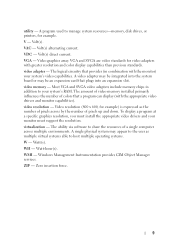
... install the appropriate video drivers and your system's RAM. Most VGA and SVGA video adapters include memory chips in combination with the monitor) your system's video capabilities. A single physical system may be integrated into an expansion slot. WMI - A program used to share the resources of a single computer across by the number of...
... install the appropriate video drivers and your system's RAM. Most VGA and SVGA video adapters include memory chips in combination with the monitor) your system's video capabilities. A single physical system may be integrated into an expansion slot. WMI - A program used to share the resources of a single computer across by the number of...

Getting Started Guide
Page 17
.... Connectors (continued) Internal Internal Secure Digital (SD) module (PowerEdge M910, M805, M905, M710HD, M710, M610x, M610) Internal Secure Digital (SD) vFlash module (PowerEdge M910, M710HD, M710, M610x, M610) USB key (PowerEdge M910, M710HD, M710, M610x, M610) One optional flash memory card slot with the iDRAC Enterprise support. One optional vFlash memory card slot for use with the internal SD module.
.... Connectors (continued) Internal Internal Secure Digital (SD) module (PowerEdge M910, M805, M905, M710HD, M710, M610x, M610) Internal Secure Digital (SD) vFlash module (PowerEdge M910, M710HD, M710, M610x, M610) USB key (PowerEdge M910, M710HD, M710, M610x, M610) One optional flash memory card slot with the iDRAC Enterprise support. One optional vFlash memory card slot for use with the internal SD module.

Getting Started Guide
Page 18
... by two integrated dual-port Broadcom 5709S Ethernet controllers. Matrox G200 video controller. 8 MB video memory. Mezzanine Cards (continued) PowerEdge M610x, M610 Up to two PCIe x8 mezzanine card slots, supporting dual-port Gb Ethernet, 10 Gb Ethernet, FC8 or FC4 Fibre Channel, or 4x ... lb) 16 Getting Started With Your System Video Controller PowerEdge M905, M805, M605, M600 PowerEdge M910, M710HD, M710, M610x, M610 ATI RN50 video controller. 32 MB video memory. PowerEdge M605, M600 Up to two PCIe Gen 2 x8 mezzanine card slots, supporting dual-port Gb Ethernet, 10 Gb Ethernet, ...
... by two integrated dual-port Broadcom 5709S Ethernet controllers. Matrox G200 video controller. 8 MB video memory. Mezzanine Cards (continued) PowerEdge M610x, M610 Up to two PCIe x8 mezzanine card slots, supporting dual-port Gb Ethernet, 10 Gb Ethernet, FC8 or FC4 Fibre Channel, or 4x ... lb) 16 Getting Started With Your System Video Controller PowerEdge M905, M805, M605, M600 PowerEdge M910, M710HD, M710, M610x, M610 ATI RN50 video controller. 32 MB video memory. PowerEdge M605, M600 Up to two PCIe Gen 2 x8 mezzanine card slots, supporting dual-port Gb Ethernet, 10 Gb Ethernet, ...

Dell PowerEdge M1000e Configuration Guide
Page 43
... manufacturing process. If the type you had to replace one server module with WWN/MAC IDs provided by inserting the SD card into an USB Memory Card Reader and viewing the file pwwn_mac.xml. no permanent changes are looking for a new server module. The mac_count tag is an optional upgrade introduced... can be reconfigured to exit. 9 Start up the analog switch and the system. Additionally, the override action only occurs when a server module is replaced, the slot-based WWN/MAC ID remains the same. 6 Select the type of switch connected to a particular...
... manufacturing process. If the type you had to replace one server module with WWN/MAC IDs provided by inserting the SD card into an USB Memory Card Reader and viewing the file pwwn_mac.xml. no permanent changes are looking for a new server module. The mac_count tag is an optional upgrade introduced... can be reconfigured to exit. 9 Start up the analog switch and the system. Additionally, the override action only occurs when a server module is replaced, the slot-based WWN/MAC ID remains the same. 6 Select the type of switch connected to a particular...
Hardware Owner's Manual
Page 102
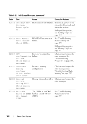
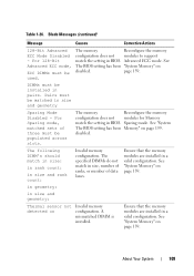
... Processors" on page 337. Check screen for 10 seconds and restart the system. Check screen for specific error messages. The DIMM in slot "##" has had a multi-bit error (MBE). Remove AC power to the system for specific error messages (see "Getting Help" on... DIMM ##. failure. Reseat DIMM. Check DIMMs. See "Troubleshooting Blade Memory" on page 297). Check screen message. General failure after video. failure. E2021 Incorrect memory configuration. E2110 Multibit Error on page 337. Table 1-25. LCD Status Messages (continued) Code...
... Processors" on page 337. Check screen for 10 seconds and restart the system. Check screen for specific error messages. The DIMM in slot "##" has had a multi-bit error (MBE). Remove AC power to the system for specific error messages (see "Getting Help" on... DIMM ##. failure. Reseat DIMM. Check DIMMs. See "Troubleshooting Blade Memory" on page 297). Check screen message. General failure after video. failure. E2021 Incorrect memory configuration. E2110 Multibit Error on page 337. Table 1-25. LCD Status Messages (continued) Code...
Hardware Owner's Manual
Page 108
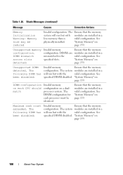
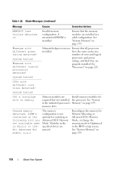
... The system modules are installed in a will run but with the valid configuration. DIMM mismatch across slots detected: Invalid memory Ensure that the memory system will run but with modules are installed in the valid configuration. Ensure that the memory configuration. Unsupported memory configuration. Maximum rank count exceeded. The following DIMM has been disabled: Invalid...
... The system modules are installed in a will run but with the valid configuration. DIMM mismatch across slots detected: Invalid memory Ensure that the memory system will run but with modules are installed in the valid configuration. Ensure that the memory configuration. Unsupported memory configuration. Maximum rank count exceeded. The following DIMM has been disabled: Invalid...
Hardware Owner's Manual
Page 109
... are installed in size, number of ranks, or number of three must be populated across slots. The following DIMM's should match in size: in rank count: in size and geometry: Thermal sensor not detected on Invalid memory configuration. See "System Memory" on page 159. A mismatched DIMM is installed. Sparing mode. disabled. See "System...
... are installed in size, number of ranks, or number of three must be populated across slots. The following DIMM's should match in size: in rank count: in size and geometry: Thermal sensor not detected on Invalid memory configuration. See "System Memory" on page 159. A mismatched DIMM is installed. Sparing mode. disabled. See "System...
Hardware Owner's Manual
Page 110
... Ensure that they are properly installed. have the same cache size, number of cores and logical processors, and power ratings, and that all processors installed. memory slots. Unused memory detected. Blade Messages (continued) Message Causes Corrective Actions MEMTEST lane failure detected on page 159. 110 About Your System System halted CPUs with no...
... Ensure that they are properly installed. have the same cache size, number of cores and logical processors, and power ratings, and that all processors installed. memory slots. Unused memory detected. Blade Messages (continued) Message Causes Corrective Actions MEMTEST lane failure detected on page 159. 110 About Your System System halted CPUs with no...

Hardware Owner's Manual
Page 114
...DIMM pairs must be installed in sequential order beginning with slot 1. Diskette missing or improperly inserted in size, speed, and technology. See "System Memory" on page 297. If the problem persists, see "Troubleshooting Blade Memory" on page 159. Diskette read failure. Replace the .... Blade Messages (continued) Message Causes Corrective Actions DIMMs should be populated in a degraded mode with slot 1. DIMMs must be matched in diskette drive. Only memory installed in size, speed, and technology. DIMMs must be populated in pairs. Mismatched or Ensure that...
...DIMM pairs must be installed in sequential order beginning with slot 1. Diskette missing or improperly inserted in size, speed, and technology. See "System Memory" on page 297. If the problem persists, see "Troubleshooting Blade Memory" on page 159. Diskette read failure. Replace the .... Blade Messages (continued) Message Causes Corrective Actions DIMMs should be populated in a degraded mode with slot 1. DIMMs must be matched in diskette drive. Only memory installed in size, speed, and technology. DIMMs must be populated in pairs. Mismatched or Ensure that...
Hardware Owner's Manual
Page 158
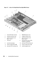
Figure 3-11. Inside a Full-Height Blade (PowerEdge M610x Shown) 56 7 4 3 12 8 14 13 12 11 10 9 1 internal SD vFalsh card slot 3 mezzanine interface card 5 optional mezzanine card Mezz1_Fab_C1 7 PCIe riser 9 hard-drive backplane 11 memory modules (B1 to A6) 14 cable management clip 158 Installing Blade Components Mezz2_Fab_B1 8 Standard PCIe cards or PCIe expansion-card blanks 10 processor CPU2 and heat sink 12 memory modules (A1 to B6) 13 processor CPU1 and heat sink 2 iDRAC6 Enterprise card 4 midplane interface card 6 optional mezzanine card -
Figure 3-11. Inside a Full-Height Blade (PowerEdge M610x Shown) 56 7 4 3 12 8 14 13 12 11 10 9 1 internal SD vFalsh card slot 3 mezzanine interface card 5 optional mezzanine card Mezz1_Fab_C1 7 PCIe riser 9 hard-drive backplane 11 memory modules (B1 to A6) 14 cable management clip 158 Installing Blade Components Mezz2_Fab_B1 8 Standard PCIe cards or PCIe expansion-card blanks 10 processor CPU2 and heat sink 12 memory modules (A1 to B6) 13 processor CPU1 and heat sink 2 iDRAC6 Enterprise card 4 midplane interface card 6 optional mezzanine card -
Hardware Owner's Manual
Page 161
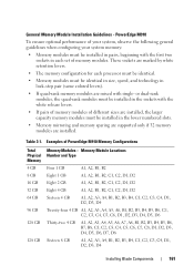
... colored levers). • If quad-rank memory modules are installed. PowerEdge M910 To ensure optimal performance of memory modules. General Memory Module Installation Guidelines - These sockets are marked by white retention levers. • The memory configuration for each set of your system, ..., and technology in the lower numbered slots. • Memory mirroring and memory sparing are supported only if 32 memory modules are mixed with the white release levers. • If pairs of memory modules of PowerEdge M910 Memory Configurations Total Physical Memory 4 GB 8 GB 16 GB 32...
... colored levers). • If quad-rank memory modules are installed. PowerEdge M910 To ensure optimal performance of memory modules. General Memory Module Installation Guidelines - These sockets are marked by white retention levers. • The memory configuration for each set of your system, ..., and technology in the lower numbered slots. • Memory mirroring and memory sparing are supported only if 32 memory modules are mixed with the white release levers. • If pairs of memory modules of PowerEdge M910 Memory Configurations Total Physical Memory 4 GB 8 GB 16 GB 32...
Hardware Owner's Manual
Page 162
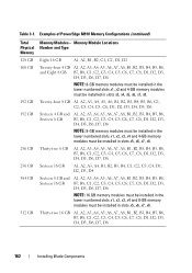
..., C3, C4, C5, C6, C7, C8, D1, D2, D3, D4, D5, D6, D7, D8 NOTE: 8-GB memory modules must be installed in the lower numbered slots x1, x2 and 4-GB memory modules must be installed in slots x5, x6, x7, x8. Thirty-two 16 GB A1, A2, A3, A4, A5, A6, A7, A8, B1..., D3, D4, D5, D6, D7, D8 NOTE: 16 GB memory modules must be installed in the lower numbered slots x1, x2, x3, x4 and 8-GB memory modules must be installed in slots x5, x6, x7, x8. Table 3-1. Examples of PowerEdge M910 Memory Configurations (continued) Total Physical Memory 128 GB 160 GB 192 GB 192 GB 256 GB...
..., C3, C4, C5, C6, C7, C8, D1, D2, D3, D4, D5, D6, D7, D8 NOTE: 8-GB memory modules must be installed in the lower numbered slots x1, x2 and 4-GB memory modules must be installed in slots x5, x6, x7, x8. Thirty-two 16 GB A1, A2, A3, A4, A5, A6, A7, A8, B1..., D3, D4, D5, D6, D7, D8 NOTE: 16 GB memory modules must be installed in the lower numbered slots x1, x2, x3, x4 and 8-GB memory modules must be installed in slots x5, x6, x7, x8. Table 3-1. Examples of PowerEdge M910 Memory Configurations (continued) Total Physical Memory 128 GB 160 GB 192 GB 192 GB 256 GB...
Hardware Owner's Manual
Page 165
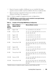
... memory modules of supported memory configurations. CAUTION: Memory module blanks must be installed in the lower numbered slots. • Memory sparing is supported if 24 memory modules are installed. (Memory mirroring is installed, the system recognizes only 63.75 GB during POST. Examples of PowerEdge M905 Memory Configurations Total System Memory Memory Modules Number and Size Memory Module..., A7, A8, B1, B2, B3, B4, B5, B6, B7, B8, C1, C2, C3, C4, D1, D2, D3, D4 *If 64 GB of memory is not supported.) Table 3-3 shows examples of different sizes are installed, the larger capacity...
... memory modules of supported memory configurations. CAUTION: Memory module blanks must be installed in the lower numbered slots. • Memory sparing is supported if 24 memory modules are installed. (Memory mirroring is installed, the system recognizes only 63.75 GB during POST. Examples of PowerEdge M905 Memory Configurations Total System Memory Memory Modules Number and Size Memory Module..., A7, A8, B1, B2, B3, B4, B5, B6, B7, B8, C1, C2, C3, C4, D1, D2, D3, D4 *If 64 GB of memory is not supported.) Table 3-3 shows examples of different sizes are installed, the larger capacity...

Hardware Owner's Manual
Page 167
... each pair must be the same size. PowerEdge M805 B1 B8 A8 A1 General Memory Module Installation Guidelines - These slots are marked by white ejector tabs. • All memory modules in pairs of identically-sized DIMMs, beginning with slots A1 and A2 (processor 1) and B1 and B2. PowerEdge M805 To ensure optimal performance of your system...
... each pair must be the same size. PowerEdge M805 B1 B8 A8 A1 General Memory Module Installation Guidelines - These slots are marked by white ejector tabs. • All memory modules in pairs of identically-sized DIMMs, beginning with slots A1 and A2 (processor 1) and B1 and B2. PowerEdge M805 To ensure optimal performance of your system...

Hardware Owner's Manual
Page 168
...in unoccupied memory sockets to maintain proper cooling airflow. CAUTION: Memory module blanks must be installed in the lower numbered slots. • Memory sparing is supported if 16 memory modules are installed. (Memory mirroring is not supported.) Table 3-5 shows examples of PowerEdge M805 Memory Configurations Total System Memory 4 GB 8 GB 8 GB 12 GB Memory Modules ...24 GB Eight 2 GB Four 4 GB Twelve 2 GB 32 GB Sixteen 2 GB 32 GB 48 GB Eight 4 GB Twelve 4 GB 64 GB* Sixteen 4 GB Memory Module Locations A1, A2, B1, B2 A1, A2, A3, A4, B1, B2, B3, B4 A1, A2, B1, B2 A1, A2, A3, A4, ...
...in unoccupied memory sockets to maintain proper cooling airflow. CAUTION: Memory module blanks must be installed in the lower numbered slots. • Memory sparing is supported if 16 memory modules are installed. (Memory mirroring is not supported.) Table 3-5 shows examples of PowerEdge M805 Memory Configurations Total System Memory 4 GB 8 GB 8 GB 12 GB Memory Modules ...24 GB Eight 2 GB Four 4 GB Twelve 2 GB 32 GB Sixteen 2 GB 32 GB 48 GB Eight 4 GB Twelve 4 GB 64 GB* Sixteen 4 GB Memory Module Locations A1, A2, B1, B2 A1, A2, A3, A4, B1, B2, B3, B4 A1, A2, B1, B2 A1, A2, A3, A4, ...
Hardware Owner's Manual
Page 172
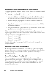
... chip, the faulty chip is not installed in corresponding slots. sockets B1 through A9 are installed, a maximum of two DIMMs per channel is one 128-bit channel. Three memory channels are assigned to CPU1; sockets 3, 6, 9 • Channel 1 - PowerEdge M710 The system supports memory mirroring if identical memory modules are installed, they operate at the speed...
... chip, the faulty chip is not installed in corresponding slots. sockets B1 through A9 are installed, a maximum of two DIMMs per channel is one 128-bit channel. Three memory channels are assigned to CPU1; sockets 3, 6, 9 • Channel 1 - PowerEdge M710 The system supports memory mirroring if identical memory modules are installed, they operate at the speed...
Hardware Owner's Manual
Page 177
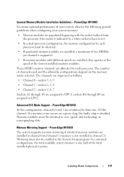
... 1 are populated beginning with the socket farthest from the processor (this socket is disabled. sockets 3, 6, 9 • Channel 1 - PowerEdge M710HD To ensure optimal performance of two DIMMs per channel is not installed in corresponding slots. General Memory Module Installation Guidelines - sockets 2, 5, 8 • Channel 2 - If a memory error occurs on the memory mode selected. Installing Blade Components 177
... 1 are populated beginning with the socket farthest from the processor (this socket is disabled. sockets 3, 6, 9 • Channel 1 - PowerEdge M710HD To ensure optimal performance of two DIMMs per channel is not installed in corresponding slots. General Memory Module Installation Guidelines - sockets 2, 5, 8 • Channel 2 - If a memory error occurs on the memory mode selected. Installing Blade Components 177
Hardware Owner's Manual
Page 182
... at the speed of the total installed physical memory. 182 Installing Blade Components Memory modules must be enabled in corresponding slots. sockets 3, 6 • Channel 1 - sockets B1 through A6 are assigned to form one -half of the slowest installed memory modules. PowerEdge M610/M610x The system supports memory mirroring if identical memory modules are installed, a maximum of two DIMMs...
... at the speed of the total installed physical memory. 182 Installing Blade Components Memory modules must be enabled in corresponding slots. sockets 3, 6 • Channel 1 - sockets B1 through A6 are assigned to form one -half of the slowest installed memory modules. PowerEdge M610/M610x The system supports memory mirroring if identical memory modules are installed, a maximum of two DIMMs...

Hardware Owner's Manual
Page 186
... must be identical in the lower numbered slots. • Memory sparing is supported if four (single-processor systems) or eight (dual-processor systems) memory modules are marked by white ejector tabs. • All memory modules in the blade must be installed in pairs of supported single- PowerEdge M605 A1 A2 A3 A4 B4 B3 General...
... must be identical in the lower numbered slots. • Memory sparing is supported if four (single-processor systems) or eight (dual-processor systems) memory modules are marked by white ejector tabs. • All memory modules in the blade must be installed in pairs of supported single- PowerEdge M605 A1 A2 A3 A4 B4 B3 General...

Hardware Owner's Manual
Page 191
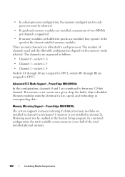
... two equal branches (0 and 1). PowerEdge M600 You can upgrade your system memory to a maximum of each channel consists of two memory module sockets: • Branch 0, Channel 0 consists of slot 1 and slot 5. • Branch 0, Channel 1 consists of slot 2 and slot 6. • Branch 1, Channel 2 consists of slot 3 and slot 7. • Branch 1, Channel 3 consists of the memory module sockets. Memory Locations - Each branch consists...
... two equal branches (0 and 1). PowerEdge M600 You can upgrade your system memory to a maximum of each channel consists of two memory module sockets: • Branch 0, Channel 0 consists of slot 1 and slot 5. • Branch 0, Channel 1 consists of slot 2 and slot 6. • Branch 1, Channel 2 consists of slot 3 and slot 7. • Branch 1, Channel 3 consists of the memory module sockets. Memory Locations - Each branch consists...


