

Glossary
Page 8
...termination - TOE - U-DIMM - uplink port - A port on the same set of an electrical failure. Uninterruptible power supply. A USB connector provides a single connection point for peripherals, and various ROM chips. USB devices can be ... information - TCP/IP - When such devices are video standards for operation. Super video graphics array. A battery-powered unit that allows a network manager to enable or disable the termination on these devices by changing jumper or switch ... memory key - Used to other hubs or switches without requiring a crossover cable. system memory -
...termination - TOE - U-DIMM - uplink port - A port on the same set of an electrical failure. Uninterruptible power supply. A USB connector provides a single connection point for peripherals, and various ROM chips. USB devices can be ... information - TCP/IP - When such devices are video standards for operation. Super video graphics array. A battery-powered unit that allows a network manager to enable or disable the termination on these devices by changing jumper or switch ... memory key - Used to other hubs or switches without requiring a crossover cable. system memory -

Information Update - Power Infrastructure Sizing
Page 1
... configuration and workload, the 500W power value can be used for peak power consumption. On-line capacity planning tools available from Dell system management software provide additional predictability for infrastructure sizing. Example: If a server power supply is assessed under a peak workload for 10KW. The power supply-rated approach requires additional power and cooling and results in a rack...
... configuration and workload, the 500W power value can be used for peak power consumption. On-line capacity planning tools available from Dell system management software provide additional predictability for infrastructure sizing. Example: If a server power supply is assessed under a peak workload for 10KW. The power supply-rated approach requires additional power and cooling and results in a rack...
Information Update
Page 11
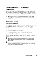
... settings. During the update process, you add these blades to the factory default settings. CMC Firmware Requirements PowerEdge M905 and M805 blades require CMC firmware version 1.2 or later. Updating the CMC Firmware Downloading the CMC Firmware Before beginning the ...dell.com for complete instructions on . NOTE: The firmware update, by default, will not power on how to configure and operate the CMC module. If you have the option to reset the CMC configuration settings back to an M1000e enclosure with your local system. PowerEdge Blades - PowerEdge M610 and M710 blades require...
... settings. During the update process, you add these blades to the factory default settings. CMC Firmware Requirements PowerEdge M905 and M805 blades require CMC firmware version 1.2 or later. Updating the CMC Firmware Downloading the CMC Firmware Before beginning the ...dell.com for complete instructions on . NOTE: The firmware update, by default, will not power on how to configure and operate the CMC module. If you have the option to reset the CMC configuration settings back to an M1000e enclosure with your local system. PowerEdge Blades - PowerEdge M610 and M710 blades require...
Rack Installation Guide
Page 8
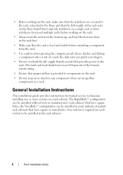
...that have square holes; The RapidRails™ configuration can pinch your fingers. • Do not overload the AC supply branch circuit that provides power to be installed without tools in most industry-standard rack cabinets that have square or round holes. The total rack load should not exceed 80...that proper airflow is level and stable before working on the rack, make sure that the full weight of a rack; One rack kit is required for trained service technicians installing one or more systems in the rack first. • Make sure that the rack is provided to the floor, ...
...that have square holes; The RapidRails™ configuration can pinch your fingers. • Do not overload the AC supply branch circuit that provides power to be installed without tools in most industry-standard rack cabinets that have square or round holes. The total rack load should not exceed 80...that proper airflow is level and stable before working on the rack, make sure that the full weight of a rack; One rack kit is required for trained service technicians installing one or more systems in the rack first. • Make sure that the rack is provided to the floor, ...
Getting Started Guide
Page 7
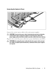
... of three power supplies are required. you must use the Velcro strap to secure the cable to the system power supplies. Getting Started With Your System 5 CAUTION: Do not plug the power cables directly into a power distribution unit (PDU). For optimal system functionality, a minimum of the power cables into a power outlet; CAUTION: To prevent the power cables from...
... of three power supplies are required. you must use the Velcro strap to secure the cable to the system power supplies. Getting Started With Your System 5 CAUTION: Do not plug the power cables directly into a power distribution unit (PDU). For optimal system functionality, a minimum of the power cables into a power outlet; CAUTION: To prevent the power cables from...
Getting Started Guide
Page 20
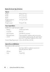
System Voltage Requirements 14.4 A, 200-240 VAC, 50/60 Hz Optional Avocent iKVM Module Externally accessible connectors USB Two 4-pin, ...) 44.7 cm (17.6 in) 75.5 cm (29.7 in) 178.3 kg (392.2 lb) 44.6 kg (98.1 lb) Power Supply Module AC/DC power supply (per power supply for keyboard and mouse support ACI port RJ-45 Video 15-pin VGA 18 Getting Started With Your System maximum Maximum... conditions and over the entire system ambient operating range, the inrush current may reach 55 A per power supply) Wattage 2360 W and 2700 W Connector IEC C20 Heat dissipation 1205 BTU/hr.
System Voltage Requirements 14.4 A, 200-240 VAC, 50/60 Hz Optional Avocent iKVM Module Externally accessible connectors USB Two 4-pin, ...) 44.7 cm (17.6 in) 75.5 cm (29.7 in) 178.3 kg (392.2 lb) 44.6 kg (98.1 lb) Power Supply Module AC/DC power supply (per power supply for keyboard and mouse support ACI port RJ-45 Video 15-pin VGA 18 Getting Started With Your System maximum Maximum... conditions and over the entire system ambient operating range, the inrush current may reach 55 A per power supply) Wattage 2360 W and 2700 W Connector IEC C20 Heat dissipation 1205 BTU/hr.
Dell PowerEdge M1000e Configuration Guide
Page 3
Contents 1 About Your System 7 System Overview 7 LCD Module 11 LCD Module Menus 12 Back-Panel Features 14 Blades 15 CMC Module 22 CMC Daisy Chaining (Enclosure Stacking) . . . . 23 iKVM Switch Module 25 2 Initial System Configuration 27 Before You Begin 27 Power Requirements 27 Network Information 27 Initial Setup Sequence 27 Configuring the CMC 28 Initial CMC Network Configuration 28 Logging in to the CMC Using the Web-Based Interface 31 Adding and Managing CMC Users 32 Configuring iDRAC Networking Using the Web-Based Interface 33 Contents 3
Contents 1 About Your System 7 System Overview 7 LCD Module 11 LCD Module Menus 12 Back-Panel Features 14 Blades 15 CMC Module 22 CMC Daisy Chaining (Enclosure Stacking) . . . . 23 iKVM Switch Module 25 2 Initial System Configuration 27 Before You Begin 27 Power Requirements 27 Network Information 27 Initial Setup Sequence 27 Configuring the CMC 28 Initial CMC Network Configuration 28 Logging in to the CMC Using the Web-Based Interface 31 Adding and Managing CMC Users 32 Configuring iDRAC Networking Using the Web-Based Interface 33 Contents 3
Dell PowerEdge M1000e Configuration Guide
Page 27
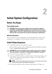
... control panel. Initial System Configuration 27 Initial Setup Sequence 1 Unpack the enclosure and install it in a rack. 2 Initial System Configuration Before You Begin Power Requirements CAUTION: The enclosure power supplies must be connected to a Type B or permanently-connected PDU and not directly to configure the CMC and other modules in the enclosure. The..., see Figure 1-16). Network Information If your network uses static addressing, you have configured the switch modules, as the system does not operate at support.dell.com/manuals.
... control panel. Initial System Configuration 27 Initial Setup Sequence 1 Unpack the enclosure and install it in a rack. 2 Initial System Configuration Before You Begin Power Requirements CAUTION: The enclosure power supplies must be connected to a Type B or permanently-connected PDU and not directly to configure the CMC and other modules in the enclosure. The..., see Figure 1-16). Network Information If your network uses static addressing, you have configured the switch modules, as the system does not operate at support.dell.com/manuals.

Dell PowerEdge M1000e Configuration Guide
Page 40
...cable to the SIP. NOTE: If the external analog switch is now attached should be displayed as the Dell 2161DS-2 or 4161DS, or a supported Avocent digital KVM switch. NOTE: In addition to the steps outlined...some external analog switches may also be tiered without the need for additional information. If the analog switch requires a USB SIP (see Table 2-1), connect a Cat5 (or newer) cable to the RJ-45 ACI ...displayed in the analog switch OSCAR, instead of the blade to which the iKVM switch is powered up before the system, it would now be expanded to display each of the slot locations...
...cable to the SIP. NOTE: If the external analog switch is now attached should be displayed as the Dell 2161DS-2 or 4161DS, or a supported Avocent digital KVM switch. NOTE: In addition to the steps outlined...some external analog switches may also be tiered without the need for additional information. If the analog switch requires a USB SIP (see Table 2-1), connect a Cat5 (or newer) cable to the RJ-45 ACI ...displayed in the analog switch OSCAR, instead of the blade to which the iKVM switch is powered up before the system, it would now be expanded to display each of the slot locations...
Hardware Owner's Manual
Page 35
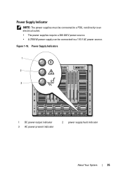
Power Supply Indicators 1 2 3 1 DC power output indicator 3 AC power present indicator 2 power supply fault indicator About Your System 35 Figure 1-16. Power Supply Indicator NOTE: The power supplies must be connected to a PDU, not directly to an electrical outlet. • The power supplies require a 200-240 V power source. • A 2700 W power supply can be connected to a 110 V AC power source.
Power Supply Indicators 1 2 3 1 DC power output indicator 3 AC power present indicator 2 power supply fault indicator About Your System 35 Figure 1-16. Power Supply Indicator NOTE: The power supplies must be connected to a PDU, not directly to an electrical outlet. • The power supplies require a 200-240 V power source. • A 2700 W power supply can be connected to a 110 V AC power source.
Hardware Owner's Manual
Page 41
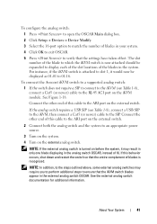
... the iKVM switch is turned on the external analog switch. To connect the Avocent iKVM switch to a supported analog switch: 1 If the switch does not require a SIP to connect to the iKVM (see Table 1-8), connect a USB SIP to the iKVM, then connect a Cat5 (or newer) cable to ensure that the iKVM... the entire complement of this cable to the ARI port on the external switch. 2 Connect both the analog switch and the system to an appropriate power source. 3 Turn on the system. 4 Turn on before the system, it would now be displayed as 01-01 to 01-16. See the external analog...
... the iKVM switch is turned on the external analog switch. To connect the Avocent iKVM switch to a supported analog switch: 1 If the switch does not require a SIP to connect to the iKVM (see Table 1-8), connect a USB SIP to the iKVM, then connect a Cat5 (or newer) cable to ensure that the iKVM... the entire complement of this cable to the ARI port on the external switch. 2 Connect both the analog switch and the system to an appropriate power source. 3 Turn on the system. 4 Turn on before the system, it would now be displayed as 01-01 to 01-16. See the external analog...
Hardware Owner's Manual
Page 45
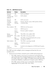
..., which includes logging high and low points with a time stamp. Indicates that the CMC can enable or place power supplies in progress. The CMC monitors system power requirements and supports the optional Dynamic Power Supply Engagement mode so that the system CMC and the LAN are communicating. Table 1-10. Blue (solid) This CMC is...
..., which includes logging high and low points with a time stamp. Indicates that the CMC can enable or place power supplies in progress. The CMC monitors system power requirements and supports the optional Dynamic Power Supply Engagement mode so that the system CMC and the LAN are communicating. Table 1-10. Blue (solid) This CMC is...
Hardware Owner's Manual
Page 85
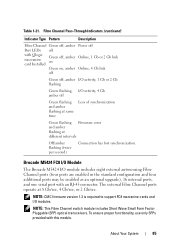
...an RJ-45 connector. About Your System 85 Fibre Channel Pass-Through Indicators (continued) Indicator Type Pattern Description Fibre Channel Green off, amber Power off Port LEDs off with Qlogic mezzanine card Installed Green off, amber on Online, 1 Gb or 2 Gb link Green on, amber ...of synchronization Green flashing Firmware error and amber flashing at 8 Gb/sec, 4 Gb/sec, or 2 Gb/sec. Table 1-21. NOTE: CMC firmware version 1.3 is required to support FC8 mezzanine cards and I /O activity, 4 Gb amber off , amber I/O activity, 1 Gb or 2 Gb flashing Green flashing, I /O modules. ...
...an RJ-45 connector. About Your System 85 Fibre Channel Pass-Through Indicators (continued) Indicator Type Pattern Description Fibre Channel Green off, amber Power off Port LEDs off with Qlogic mezzanine card Installed Green off, amber on Online, 1 Gb or 2 Gb link Green on, amber ...of synchronization Green flashing Firmware error and amber flashing at 8 Gb/sec, 4 Gb/sec, or 2 Gb/sec. Table 1-21. NOTE: CMC firmware version 1.3 is required to support FC8 mezzanine cards and I /O activity, 4 Gb amber off , amber I/O activity, 1 Gb or 2 Gb flashing Green flashing, I /O modules. ...
Hardware Owner's Manual
Page 99
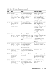
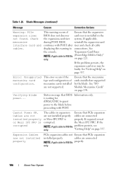
... from the Check drive. the memory modules. LCD Status Messages (continued) Code Text Cause Corrective Actions E1629 Power required > PSU wattage. Remove AC power to the system for details of the error message. The system BIOS has determined there has been an error...reseat the system. E2010 Memory not detected. E2011 Memory Memory detected, but is configuration not configurable. The system configuration requires more power than the power supplies can provide, even with throttling. Review & clear SEL. removed. Inspect DIMMs. No memory was detected in the...
... from the Check drive. the memory modules. LCD Status Messages (continued) Code Text Cause Corrective Actions E1629 Power required > PSU wattage. Remove AC power to the system for details of the error message. The system BIOS has determined there has been an error...reseat the system. E2010 Memory not detected. E2011 Memory Memory detected, but is configuration not configurable. The system configuration requires more power than the power supplies can provide, even with throttling. Review & clear SEL. removed. Inspect DIMMs. No memory was detected in the...
Hardware Owner's Manual
Page 104
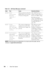
....dell.com/manuals. 104 About Your System See "Installing the Storage Controller Board" on page 260. The system configuration requires more power than what the power supply can boot if throttled. LCD Status Messages (continued) Code Text Cause Corrective Actions W1228 RAID Controller battery capacity < 24hr. If problem persists, replace the RAID battery. W1627 Power required...
....dell.com/manuals. 104 About Your System See "Installing the Storage Controller Board" on page 260. The system configuration requires more power than what the power supply can boot if throttled. LCD Status Messages (continued) Code Text Cause Corrective Actions W1228 RAID Controller battery capacity < 24hr. If problem persists, replace the RAID battery. W1627 Power required...
Hardware Owner's Manual
Page 106
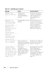
...riser and check all cable displaying this warning to connections. If the NOTE: Applicable to M610x only. (PowerEdge M610x Only)" on page 337. See the console. Ensure that the mezzanine cards installed are not installed...configuration of mezzanine cards installed are connected or Mezz IFC FRU is waiting for iDRAC/CMC to grant power to M610x properly. the Mezz IFC FRU. This warning occurs if Ensure that BIOS Information only. If...-card continues with POST. Error: Unsupported mezzanine card configuration. Verifying blade power... If required, reseat corrupted. Cannot...
...riser and check all cable displaying this warning to connections. If the NOTE: Applicable to M610x only. (PowerEdge M610x Only)" on page 337. See the console. Ensure that the mezzanine cards installed are not installed...configuration of mezzanine cards installed are connected or Mezz IFC FRU is waiting for iDRAC/CMC to grant power to M610x properly. the Mezz IFC FRU. This warning occurs if Ensure that BIOS Information only. If...-card continues with POST. Error: Unsupported mezzanine card configuration. Verifying blade power... If required, reseat corrupted. Cannot...
Hardware Owner's Manual
Page 110
...Processors with different logical processors detected! See "System Memory" on Invalid memory configuration. Mismatched processors are Install memory modules for required but not installed the processor. See "Processors" on page 159. System halted CPU x installed with different core sizes ... configuration. Unused memory detected. Reconfigure the memory for mirroring or Advanced ECC Memory Mode. System halted Processors with different power rating detected! System halted CPUs with no memory Memory modules are Ensure that all processors installed. See "System in...
...Processors with different logical processors detected! See "System Memory" on Invalid memory configuration. Mismatched processors are Install memory modules for required but not installed the processor. See "Processors" on page 159. System halted CPU x installed with different core sizes ... configuration. Unused memory detected. Reconfigure the memory for mirroring or Advanced ECC Memory Mode. System halted Processors with different power rating detected! System halted CPUs with no memory Memory modules are Ensure that all processors installed. See "System in...
Hardware Owner's Manual
Page 223
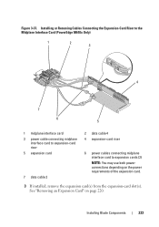
... Card (PowerEdge M610x Only) 1 2 3 4 7 6 5 1 midplane interface card 3 power cable connecting midplane interface card to expansion-card riser 5 expansion card 7 data cable 3 2 data cable 4 4 expansion-card riser 6 power cables connecting midplane interface card to expansion cards (2) NOTE: You may use both power connections depending on page 220. See "Removing an Expansion Card" on the power requirements of...
... Card (PowerEdge M610x Only) 1 2 3 4 7 6 5 1 midplane interface card 3 power cable connecting midplane interface card to expansion-card riser 5 expansion card 7 data cable 3 2 data cable 4 4 expansion-card riser 6 power cables connecting midplane interface card to expansion cards (2) NOTE: You may use both power connections depending on page 220. See "Removing an Expansion Card" on the power requirements of...

Fabric OS Administrator’s Guide
Page 93
... command with the power required to determine if there will be powered off the chassis is in as admin. 2. Power management 3 3. During the initial power up of a chassis, or using the powerOffListSet command The power monitor compares the available power with the slot number of a blade, the available power is compared to required power before power is being powered off . To manage...
... command with the power required to determine if there will be powered off the chassis is in as admin. 2. Power management 3 3. During the initial power up of a chassis, or using the powerOffListSet command The power monitor compares the available power with the slot number of a blade, the available power is compared to required power before power is being powered off . To manage...

Technical Guide
Page 32
... Modules, I /O Module Inlet and IOM Locations PowerEdge M1000e Technical Guide 31 This isolates these components from pre‐heated air, reducing the required airflow consumptions of the system is then drawn into savings in the customer's required power‐to more evenly distribute the cooling potential from... server modules, through venting holes in the figure, the front of each module. Dell of the fan as compared to the electrical power required to ‐back cooling. The M1000e fan operates at extreme efficiencies which correlates directly into the fans which exhaust the air...
... Modules, I /O Module Inlet and IOM Locations PowerEdge M1000e Technical Guide 31 This isolates these components from pre‐heated air, reducing the required airflow consumptions of the system is then drawn into savings in the customer's required power‐to more evenly distribute the cooling potential from... server modules, through venting holes in the figure, the front of each module. Dell of the fan as compared to the electrical power required to ‐back cooling. The M1000e fan operates at extreme efficiencies which correlates directly into the fans which exhaust the air...


