
EMC Installation and Service Manual
Page 5
... 110 GPU cabling diagrams...111 SXM2 Graphics processing unit...114 Removing the NVLink Air Shroud...114 Removing the SXM2-GPU Heat Sink...115 Removing the SXM2 GPU...116 Removing the NVLink Board...118 Installing the NVLink Board...119 Installing an SXM2 GPU...119 Installing the SXM2-GPU Heat... Sink...121 Installing the NVLink Air Shroud...123 Power supply units...123 Removing a power supply unit blank...124...
... 110 GPU cabling diagrams...111 SXM2 Graphics processing unit...114 Removing the NVLink Air Shroud...114 Removing the SXM2-GPU Heat Sink...115 Removing the SXM2 GPU...116 Removing the NVLink Board...118 Installing the NVLink Board...119 Installing an SXM2 GPU...119 Installing the SXM2-GPU Heat... Sink...121 Installing the NVLink Air Shroud...123 Power supply units...123 Removing a power supply unit blank...124...

EMC Installation and Service Manual
Page 11
... 6. System board 2. Riser 1A (Low-profile PCIe expansion cards: Slots 1 and 2) Dell EMC PowerEdge C4140 system overview 11 OpenManage Mobile (OMM) label 5. Figure 7. PCIe switch board 4. Information tag 9. Service Tag 2. The optional two 2.5-inch cabled SATA SSDs is supported on the switchboard, NVLink, or cabled configuration (B, C, G, K, and M). PCIe GPU (4) 3. Network daughter card (NDC) 11...
... 6. System board 2. Riser 1A (Low-profile PCIe expansion cards: Slots 1 and 2) Dell EMC PowerEdge C4140 system overview 11 OpenManage Mobile (OMM) label 5. Figure 7. PCIe switch board 4. Information tag 9. Service Tag 2. The optional two 2.5-inch cabled SATA SSDs is supported on the switchboard, NVLink, or cabled configuration (B, C, G, K, and M). PCIe GPU (4) 3. Network daughter card (NDC) 11...

EMC Installation and Service Manual
Page 12
PCIe switch board 4. NVLink board 5. NVLink air shroud 4. PSU (2) Network daughter card (NDC) 11. DIMMs (24) 6. System board 2. PSU (2) 8. Configuration K 1. Cooling fan (8) 6. Processor and heat sink (2) 7. Air shroud 12 Dell EMC PowerEdge C4140 system overview 2. Figure 8. Information tag 9. Cooling fan (8) 5. Configuration G 1. Riser 2A (Low-profile PCIe expansion card: Slot 3) 10. PCIe GPU (4) 3. Riser 1A (Low-profile PCIe expansion cards: Slots 1 and 2) Figure 9. NVLink Heat sink and processor (4) 3.
PCIe switch board 4. NVLink board 5. NVLink air shroud 4. PSU (2) Network daughter card (NDC) 11. DIMMs (24) 6. System board 2. PSU (2) 8. Configuration K 1. Cooling fan (8) 6. Processor and heat sink (2) 7. Air shroud 12 Dell EMC PowerEdge C4140 system overview 2. Figure 8. Information tag 9. Cooling fan (8) 5. Configuration G 1. Riser 2A (Low-profile PCIe expansion card: Slot 3) 10. PCIe GPU (4) 3. Riser 1A (Low-profile PCIe expansion cards: Slots 1 and 2) Figure 9. NVLink Heat sink and processor (4) 3.

EMC Installation and Service Manual
Page 13
...Dell EMC PowerEdge C4140 system overview 13 Riser 2A (Low-profile PCIe expansion card: Slot 3) 10. Riser 2A (Low-profile PCIe expansion card: Slot 3) 11. Rear SATA SSD cage 8. Network daughter card (NDC) 11. Information tag 9. Cooling fan (8) 6. System board 14. Network daughter card (NDC) 12. Information tag 9. NVLink... board 5. Air shroud 7. Riser 1A (Low-profile PCIe expansion cards: Slots 1 and 2) 13. Riser 1A (Low-profile PCIe expansion cards: Slots 1 and 2) 12. Processor and heat sink (2) Figure 10. NVLink air shroud 4. System ...
...Dell EMC PowerEdge C4140 system overview 13 Riser 2A (Low-profile PCIe expansion card: Slot 3) 10. Riser 2A (Low-profile PCIe expansion card: Slot 3) 11. Rear SATA SSD cage 8. Network daughter card (NDC) 11. Information tag 9. Cooling fan (8) 6. System board 14. Network daughter card (NDC) 12. Information tag 9. NVLink... board 5. Air shroud 7. Riser 1A (Low-profile PCIe expansion cards: Slots 1 and 2) 13. Riser 1A (Low-profile PCIe expansion cards: Slots 1 and 2) 12. Processor and heat sink (2) Figure 10. NVLink air shroud 4. System ...
EMC Installation and Service Manual
Page 23
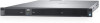
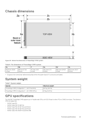
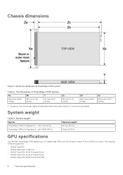
... inches) Table 7. with PCIe GPUs) PowerEdge C4140 (Configuration K - Chassis dimensions Figure 22. The dimensions of PowerEdge C4140 system Table 6. with SXM2 GPUs) Maximum weight 22.1 kg (48.7 lb) 24 kg (52.91 lb) GPU specifications The Dell EMC PowerEdge C4140 supports up to the nominal rear wall ...external surface where the system board I/O connectors are supported: • NVIDIA Tesla P40 • NVIDIA Tesla P100 12 GB PCIe • NVIDIA Tesla P100 16 GB PCIe and NVLink • NVIDIA...
... inches) Table 7. with PCIe GPUs) PowerEdge C4140 (Configuration K - Chassis dimensions Figure 22. The dimensions of PowerEdge C4140 system Table 6. with SXM2 GPUs) Maximum weight 22.1 kg (48.7 lb) 24 kg (52.91 lb) GPU specifications The Dell EMC PowerEdge C4140 supports up to the nominal rear wall ...external surface where the system board I/O connectors are supported: • NVIDIA Tesla P40 • NVIDIA Tesla P100 12 GB PCIe • NVIDIA Tesla P100 16 GB PCIe and NVLink • NVIDIA...

EMC Installation and Service Manual
Page 29
... dust, zinc whiskers, or other conductive particles. Table 25. Conductive dust Air must have a deliquescent point less than 60% relative humidity. Configuration M CPU Power Dissipation / NVLink SXM2 2x 70 W 2x 85 W 300W 24 24 2x 10⁵ W 23 2x 125 W 2x 130 W 23 22 2x 140 W 22 2x 150 W 20 2x... or gaseous pollution exceed the specified limitations and result in the air must have the MERV11 or MERV13 filtration. Table 22. Configuration K CPU Power Dissipation / NVLink SXM2 2x 70 W 2x 85 W 300W 25 24 2x 10⁵ W 2x 125 W 22 21 2x 130 W 20 2x 140 W 19 2x 150 W 18 ...
... dust, zinc whiskers, or other conductive particles. Table 25. Conductive dust Air must have a deliquescent point less than 60% relative humidity. Configuration M CPU Power Dissipation / NVLink SXM2 2x 70 W 2x 85 W 300W 24 24 2x 10⁵ W 23 2x 125 W 2x 130 W 23 22 2x 140 W 22 2x 150 W 20 2x... or gaseous pollution exceed the specified limitations and result in the air must have the MERV11 or MERV13 filtration. Table 22. Configuration K CPU Power Dissipation / NVLink SXM2 2x 70 W 2x 85 W 300W 25 24 2x 10⁵ W 2x 125 W 22 21 2x 130 W 20 2x 140 W 19 2x 150 W 18 ...

EMC Installation and Service Manual
Page 63
Removing the system air shroud for B, C, G, K and M configurations 2. Steps 1. Holding the blue touch points, lift the NVLink air shroud from the NVLink board. PowerEdge C4140 installing and removing system components 63 Holding the blue touch points, lift the air shroud out of data. 1. Follow the procedure listed in Before working ...
Removing the system air shroud for B, C, G, K and M configurations 2. Steps 1. Holding the blue touch points, lift the NVLink air shroud from the NVLink board. PowerEdge C4140 installing and removing system components 63 Holding the blue touch points, lift the air shroud out of data. 1. Follow the procedure listed in Before working ...

EMC Installation and Service Manual
Page 65
Lower the NVLink air shroud into the NVLink board until it is firmly seated. Installing the air shroud for K and M Configurations Next steps Follow the procedure listed in After working inside your system on the graphics heat sink. 4. Figure 30. Figure 31. PowerEdge C4140 installing and removing system components 65 Align the guide slots on the NVLink air shroud with the screws on page 58. Installing the system air shroud or B, C, G, K and M Configurations 3.
Lower the NVLink air shroud into the NVLink board until it is firmly seated. Installing the air shroud for K and M Configurations Next steps Follow the procedure listed in After working inside your system on the graphics heat sink. 4. Figure 30. Figure 31. PowerEdge C4140 installing and removing system components 65 Align the guide slots on the NVLink air shroud with the screws on page 58. Installing the system air shroud or B, C, G, K and M Configurations 3.

EMC Installation and Service Manual
Page 98
Graphics processing unit The Dell EMC PowerEdge C4140 supports two form factors of GPUs: • Four PCIe GPUs supported with the GPU switch board or system board. • Four SXM2 GPUs supported with a faulty fan. • All GPUs must be impacted when operating above the maximum temperature limit or with the NVLink board. Remove the...
Graphics processing unit The Dell EMC PowerEdge C4140 supports two form factors of GPUs: • Four PCIe GPUs supported with the GPU switch board or system board. • Four SXM2 GPUs supported with a faulty fan. • All GPUs must be impacted when operating above the maximum temperature limit or with the NVLink board. Remove the...

EMC Installation and Service Manual
Page 113
GPU 4 and 5 cables on the GPU switch board 10. GPU 7 power cable 4. NVLink board 2. Configuration K: Cabling dual processor systems with SXM2 GPUs- GPU 5 power cable 2. Configuration M: Cabling dual processor systems with SXM2 GPUs 1. GPU 7 power cable PowerEdge C4140 installing and removing system components 113 9. GPU switch board to system board cable 13. system board...
GPU 4 and 5 cables on the GPU switch board 10. GPU 7 power cable 4. NVLink board 2. Configuration K: Cabling dual processor systems with SXM2 GPUs- GPU 5 power cable 2. Configuration M: Cabling dual processor systems with SXM2 GPUs 1. GPU 7 power cable PowerEdge C4140 installing and removing system components 113 9. GPU switch board to system board cable 13. system board...

EMC Installation and Service Manual
Page 114
... section. 2. Steps Lift and remove the NVLink air shroud from the NVLink board. Remove the NVLink air shroud. 2. Remove the SXM2 GPU. 4. Install the NVLink air shroud. Removing the NVLink Air Shroud Prerequisites 1. Follow the safety guidelines listed in Before working inside your system. Removing NVLink air shroud 114 PowerEdge C4140 installing and removing system components GPU 4 and...
... section. 2. Steps Lift and remove the NVLink air shroud from the NVLink board. Remove the NVLink air shroud. 2. Remove the SXM2 GPU. 4. Install the NVLink air shroud. Removing the NVLink Air Shroud Prerequisites 1. Follow the safety guidelines listed in Before working inside your system. Removing NVLink air shroud 114 PowerEdge C4140 installing and removing system components GPU 4 and...

EMC Installation and Service Manual
Page 115
... the SXM2-GPU heat sink screws 2. Remove the NVLink air shroud. Figure 86. Return to the first screw to the screw you loosened. Follow the procedure listed in Before working inside your system. 3. PowerEdge C4140 installing and removing system components 115 Loosen the screw ...diagonally opposite to loosen it completely. 4. Lift the heat sink from the NVLink board. Repeat the procedure for the remaining two screws. 3.
... the SXM2-GPU heat sink screws 2. Remove the NVLink air shroud. Figure 86. Return to the first screw to the screw you loosened. Follow the procedure listed in Before working inside your system. 3. PowerEdge C4140 installing and removing system components 115 Loosen the screw ...diagonally opposite to loosen it completely. 4. Lift the heat sink from the NVLink board. Repeat the procedure for the remaining two screws. 3.

EMC Installation and Service Manual
Page 116
... the captive screws that secure the SXM2 GPU to the SXM2 GPU, ensure that you loosen the screws in a descending order, as labeled on the NVLink board. 116 PowerEdge C4140 installing and removing system components Remove the SXM2-GPU heat sink. Lift and remove the SXM2 GPU out of its socket on the...
... the captive screws that secure the SXM2 GPU to the SXM2 GPU, ensure that you loosen the screws in a descending order, as labeled on the NVLink board. 116 PowerEdge C4140 installing and removing system components Remove the SXM2-GPU heat sink. Lift and remove the SXM2 GPU out of its socket on the...

EMC Installation and Service Manual
Page 117
Figure 89. If required, install the socket protective caps on the NVLink board. Installing the socket protective caps Next steps 1. Figure 88. Install a SXM2 GPU. PowerEdge C4140 installing and removing system components 117 Remove the NVLink board. 2. Removing the SXM2 GPU 3.
Figure 89. If required, install the socket protective caps on the NVLink board. Installing the socket protective caps Next steps 1. Figure 88. Install a SXM2 GPU. PowerEdge C4140 installing and removing system components 117 Remove the NVLink board. 2. Removing the SXM2 GPU 3.

EMC Installation and Service Manual
Page 118
... Next steps 1. Follow the procedure listed in the Safety instructions section. 2. Remove the following components: a. NVLink air shroud b. Figure 90. SXM2 GPU(s) CAUTION: Disconnect the data cable from the NVLink board. Install the NVLink board. 118 PowerEdge C4140 installing and removing system components Disconnect the expansion card riser cable from the system board and then...
... Next steps 1. Follow the procedure listed in the Safety instructions section. 2. Remove the following components: a. NVLink air shroud b. Figure 90. SXM2 GPU(s) CAUTION: Disconnect the data cable from the NVLink board. Install the NVLink board. 118 PowerEdge C4140 installing and removing system components Disconnect the expansion card riser cable from the system board and then...

EMC Installation and Service Manual
Page 119
...heat sink. 3. Follow the safety guidelines listed in the PCIe connectors. 3. Tighten the thumbscrews to secure the NVLink board to engage the slots on the NVLink board tray with the guide pins on the front inner wall of the chassis. 2. Slide it to the ... Prerequisites CAUTION: To avoid any damage to the system board. Next steps 1. Installing the NVLink Board Prerequisites Follow the safety guidelines listed in ascending order starting from the screw numbered 1, on the NVLink board. 1. PowerEdge C4140 installing and removing system components 119 Install air shroud. 4.
...heat sink. 3. Follow the safety guidelines listed in the PCIe connectors. 3. Tighten the thumbscrews to secure the NVLink board to engage the slots on the NVLink board tray with the guide pins on the front inner wall of the chassis. 2. Slide it to the ... Prerequisites CAUTION: To avoid any damage to the system board. Next steps 1. Installing the NVLink Board Prerequisites Follow the safety guidelines listed in ascending order starting from the screw numbered 1, on the NVLink board. 1. PowerEdge C4140 installing and removing system components 119 Install air shroud. 4.

EMC Installation and Service Manual
Page 120
...GPU. 5. Unpack the new SXM2 GPU. 2. Align the guide pin on the SXM2 GPU card with the pin-1 on the NVLink board. 3. Locate the socket on the NVLink board along with the guide pins, then place the SXM2 GPU socket. 6. Steps 1. Removing the socket protective caps 4. Tighten... captive screws in Before working inside your system. Figure 92. Follow the procedure listed in ascending order as labeled on the NVLink board. 2. If installed, remove the socket protective caps from the SXM2 GPU sockets on the NVlink board. 120 PowerEdge C4140 installing and removing system components
...GPU. 5. Unpack the new SXM2 GPU. 2. Align the guide pin on the SXM2 GPU card with the pin-1 on the NVLink board. 3. Locate the socket on the NVLink board along with the guide pins, then place the SXM2 GPU socket. 6. Steps 1. Removing the socket protective caps 4. Tighten... captive screws in Before working inside your system. Figure 92. Follow the procedure listed in ascending order as labeled on the NVLink board. 2. If installed, remove the socket protective caps from the SXM2 GPU sockets on the NVlink board. 120 PowerEdge C4140 installing and removing system components

EMC Installation and Service Manual
Page 121
.... Steps 1. CAUTION: Applying too much thermal grease can result in excess grease coming in contact with your system. Installing the SXM2-GPU Heat Sink Prerequisites 1. PowerEdge C4140 installing and removing system components 121 If you use only. Follow the procedure listed in the Safety instructions section. 2. Align the screws on the heat... a clean lint-free cloth. 2. Using the thermal grease syringe included with and contaminating the processor socket. Figure 93. Installing SXM2 GPU Next steps 1. Install the NVLink air shroud.
.... Steps 1. CAUTION: Applying too much thermal grease can result in excess grease coming in contact with your system. Installing the SXM2-GPU Heat Sink Prerequisites 1. PowerEdge C4140 installing and removing system components 121 If you use only. Follow the procedure listed in the Safety instructions section. 2. Align the screws on the heat... a clean lint-free cloth. 2. Using the thermal grease syringe included with and contaminating the processor socket. Figure 93. Installing SXM2 GPU Next steps 1. Install the NVLink air shroud.

EMC Installation and Service Manual
Page 123
... more information, see the Technical specifications section. PowerEdge C4140 installing and removing system components 123 NOTE: When two identical PSUs are installed, both PSUs when Hot Spare is low in Before working inside your system. Installing the NVLink Air Shroud Prerequisites 1. Mixing PSUs from both...power rating. Installing a NVLink air shroud Power supply units Your system supports two 2400 W or 2000 W AC PSUs or two PSUs (one of label. Follow the procedure listed in order to the system equally from previous generations of PowerEdge servers is firmly seated....
... more information, see the Technical specifications section. PowerEdge C4140 installing and removing system components 123 NOTE: When two identical PSUs are installed, both PSUs when Hot Spare is low in Before working inside your system. Installing the NVLink Air Shroud Prerequisites 1. Mixing PSUs from both...power rating. Installing a NVLink air shroud Power supply units Your system supports two 2400 W or 2000 W AC PSUs or two PSUs (one of label. Follow the procedure listed in order to the system equally from previous generations of PowerEdge servers is firmly seated....
EMC Technical Specifications
Page 6
... Table 3. with SXM2 GPUs) Maximum weight 22.1 kg (48.7 lb) 24 kg (52.91 lb) GPU specifications The Dell EMC PowerEdge C4140 supports up to the nominal rear wall external surface where the system board I/O connectors are supported: • NVIDIA Tesla P40 ...16 GB PCIe and NVLink • NVIDIA Tesla V100 32GB PCIe and NVLINK 6 Technical specifications The following GPUs are located. Zb goes to 4 double wide GPUs, with PCIe GPUs) PowerEdge C4140 (Configuration K - The dimensions of PowerEdge C4140 system Table 2. Details the dimensions of PowerEdge C4140 system Xa Xb ...
... Table 3. with SXM2 GPUs) Maximum weight 22.1 kg (48.7 lb) 24 kg (52.91 lb) GPU specifications The Dell EMC PowerEdge C4140 supports up to the nominal rear wall external surface where the system board I/O connectors are supported: • NVIDIA Tesla P40 ...16 GB PCIe and NVLink • NVIDIA Tesla V100 32GB PCIe and NVLINK 6 Technical specifications The following GPUs are located. Zb goes to 4 double wide GPUs, with PCIe GPUs) PowerEdge C4140 (Configuration K - The dimensions of PowerEdge C4140 system Table 2. Details the dimensions of PowerEdge C4140 system Xa Xb ...
