Getting Started Guide
Page 6
... voltages and temperatures, and works in high-resolution modes. • Systems management software and documentation CDs. For more information on support.dell.com. • CDs included with the systems management software. • Back-panel connectors include keyboard, video, mouse, serial, two... controller. • Serial connector for configuring and managing your rack solution describes how to troubleshoot the system and install or replace system components. The Hardware Owner's Manual is included with your system. 4 Getting Started With Your System For more information ...
... voltages and temperatures, and works in high-resolution modes. • Systems management software and documentation CDs. For more information on support.dell.com. • CDs included with the systems management software. • Back-panel connectors include keyboard, video, mouse, serial, two... controller. • Serial connector for configuring and managing your rack solution describes how to troubleshoot the system and install or replace system components. The Hardware Owner's Manual is included with your system. 4 Getting Started With Your System For more information ...
Hardware Owner's Manual (PDF)
Page 4
... 45 Opening the System 46 Closing the System 47 Cooling Shroud 47 Removing the Cooling Shroud 47 Installing the Cooling Shroud 48 System Battery 49 Replacing the System Battery 49 Optical Drive 50 Removing the Optical Drive 50 Installing the Optical Drive 51 Configuring the Boot Drive 52 Hard Drives 52...
... 45 Opening the System 46 Closing the System 47 Cooling Shroud 47 Removing the Cooling Shroud 47 Installing the Cooling Shroud 48 System Battery 49 Replacing the System Battery 49 Optical Drive 50 Removing the Optical Drive 50 Installing the Optical Drive 51 Configuring the Boot Drive 52 Hard Drives 52...
Hardware Owner's Manual (PDF)
Page 5
... Card 66 Installing the Riser Card 67 System Memory 67 Memory Module Installation Guidelines 68 Installing Memory Modules 69 Removing Memory Modules 70 Processor 70 Replacing the Processor 71 Control Panel Assembly (Service-Only Procedure 73 Removing the Control Panel Assembly 73 Installing the Control Panel Assembly 74 System Board (Service...
... Card 66 Installing the Riser Card 67 System Memory 67 Memory Module Installation Guidelines 68 Installing Memory Modules 69 Removing Memory Modules 70 Processor 70 Replacing the Processor 71 Control Panel Assembly (Service-Only Procedure 73 Removing the Control Panel Assembly 73 Installing the Control Panel Assembly 74 System Board (Service...
Hardware Owner's Manual (PDF)
Page 16
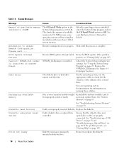
... BIOS update. See "Using the System Setup Program" on running these utilities. necessary, replace them. Ensure that the diskette drive and optical drive cables are properly connected. Reinsert or replace the diskette. 16 About Your System NVRAM_CLR jumper NVRAM_CLR jumper is complete. See Figure 6-1... BIOS Update Attempt Failed! Diskette read the data. If the problem persists, see "Getting Help" on page 103. Replace the diskette. If the problem persists, see "Getting Help" on page 103. For the operating system, run the appropriate utility to On...
... BIOS update. See "Using the System Setup Program" on running these utilities. necessary, replace them. Ensure that the diskette drive and optical drive cables are properly connected. Reinsert or replace the diskette. 16 About Your System NVRAM_CLR jumper NVRAM_CLR jumper is complete. See Figure 6-1... BIOS Update Attempt Failed! Diskette read the data. If the problem persists, see "Getting Help" on page 103. Replace the diskette. If the problem persists, see "Getting Help" on page 103. For the operating system, run the appropriate utility to On...
Hardware Owner's Manual (PDF)
Page 17
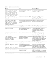
...Verify that the RAC is properly installed. keyboard. This message is faulty. Run the System Setup program to carry out the command. Replace or reconfigure the DIMMs. See "System Memory" on page 103. faulty connected. Keyboard fuse has failed. If the problem persists, the...page 29. faulty keyboard; The installed memory modules are installed in size, speed and rank. About Your System 17 Replace the keyboard. Loose or improperly connected mouse Replace the mouse. Gate A20 failure Faulty keyboard controller (faulty system board). See "Using the System Setup Program" on...
...Verify that the RAC is properly installed. keyboard. This message is faulty. Run the System Setup program to carry out the command. Replace or reconfigure the DIMMs. See "System Memory" on page 103. faulty connected. Keyboard fuse has failed. If the problem persists, the...page 29. faulty keyboard; The installed memory modules are installed in size, speed and rank. About Your System 17 Replace the keyboard. Loose or improperly connected mouse Replace the mouse. Gate A20 failure Faulty keyboard controller (faulty system board). See "Using the System Setup Program" on...
Hardware Owner's Manual (PDF)
Page 20
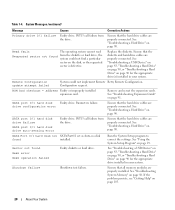
... Drive" on page 90, or "Troubleshooting a Hard Drive" on the disk, or the requested sector is defective. Configuration request. INT13 call failure from the drive. Replace the diskette. See "Troubleshooting a Hard Drive" on page 88. Sector not found installed. See "Troubleshooting System Memory" on page 90. Ensure that the hard drive...
... Drive" on page 90, or "Troubleshooting a Hard Drive" on the disk, or the requested sector is defective. Configuration request. INT13 call failure from the drive. Replace the diskette. See "Troubleshooting a Hard Drive" on page 88. Sector not found installed. See "Troubleshooting System Memory" on page 90. Ensure that the hard drive...
Hardware Owner's Manual (PDF)
Page 22
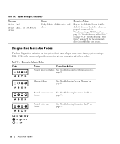
... causes and possible corrective actions associated with these codes. See "Troubleshooting System Memory" on page 91. = yellow = green = off 22 About Your System Corrective Actions Replace the diskette. Diagnostics Indicator Codes The four diagnostics indicators on failure. A B C D Memory failure. A B C D A B C D A B C D Possible expansion card See "Troubleshooting Expansion Cards" on the system front panel...
... causes and possible corrective actions associated with these codes. See "Troubleshooting System Memory" on page 91. = yellow = green = off 22 About Your System Corrective Actions Replace the diskette. Diagnostics Indicator Codes The four diagnostics indicators on failure. A B C D Memory failure. A B C D A B C D A B C D Possible expansion card See "Troubleshooting Expansion Cards" on the system front panel...

Hardware Owner's Manual (PDF)
Page 47
See Figure 3-3. 4 Replace the system in the rack, and reconnect the peripheral cables. 5 Reconnect the system to secure the cover. Installing System Components 47 See Figure 3-4. 3 Remove the ...
See Figure 3-3. 4 Replace the system in the rack, and reconnect the peripheral cables. 5 Reconnect the system to secure the cover. Installing System Components 47 See Figure 3-4. 3 Remove the ...

Hardware Owner's Manual (PDF)
Page 49
System Battery Replacing the System Battery CAUTION: Only trained service technicians are authorized to remove the system cover and access any procedure, see your fingers and pull it ... Figure 3-5. 7 Push the new battery into the battery socket as shown in Figure 3-5. See "Removing the Cooling Shroud" on page 46. 3 Remove the cooling shroud. Replacing the Battery 1 1 battery 2 3 2 battery socket 3 retention tab Installing System Components 49 Figure 3-5. See "Using the System Setup Program" on the system board. See "Removing the...
System Battery Replacing the System Battery CAUTION: Only trained service technicians are authorized to remove the system cover and access any procedure, see your fingers and pull it ... Figure 3-5. 7 Push the new battery into the battery socket as shown in Figure 3-5. See "Removing the Cooling Shroud" on page 46. 3 Remove the cooling shroud. Replacing the Battery 1 1 battery 2 3 2 battery socket 3 retention tab Installing System Components 49 Figure 3-5. See "Using the System Setup Program" on the system board. See "Removing the...
Hardware Owner's Manual (PDF)
Page 63
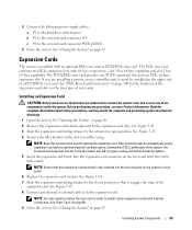
... a PCI-X/PCIe riser card. Installing System Components 63 Expansion Cards The system is also inserted into the expansion-card connector on the chassis's back panel. 6 Replace the expansion-card retainer. Filler brackets must be using. See Figure 3-15. 8 Connect any of the system and aid in order to the expansion card...
... a PCI-X/PCIe riser card. Installing System Components 63 Expansion Cards The system is also inserted into the expansion-card connector on the chassis's back panel. 6 Replace the expansion-card retainer. Filler brackets must be using. See Figure 3-15. 8 Connect any of the system and aid in order to the expansion card...
Hardware Owner's Manual (PDF)
Page 66
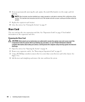
...the empty card-slot opening. See "Closing the System" on page 63 for complete information about safety precautions, working inside the system. 7 Replace the expansion-card retainer. 8 Close the system. Removing the Riser Card CAUTION: Only trained service technicians are permanently removing the card..., replace the metal filler bracket over empty expansion-card slots to maintain FCC certification of the system. See Figure 3-16. 4 Lift the ...
...the empty card-slot opening. See "Closing the System" on page 63 for complete information about safety precautions, working inside the system. 7 Replace the expansion-card retainer. 8 Close the system. Removing the Riser Card CAUTION: Only trained service technicians are permanently removing the card..., replace the metal filler bracket over empty expansion-card slots to maintain FCC certification of the system. See Figure 3-16. 4 Lift the ...

Hardware Owner's Manual (PDF)
Page 71
.... See "Opening the System" on page 47. 3 Using a #2 Phillips screwdriver, loosen the four captive screws that secure the heat sink to loosen from the socket. Replacing the Processor CAUTION: Only trained service technicians are authorized to remove the system cover and access any procedure, see your Product Information Guide for the...
.... See "Opening the System" on page 47. 3 Using a #2 Phillips screwdriver, loosen the four captive screws that secure the heat sink to loosen from the socket. Replacing the Processor CAUTION: Only trained service technicians are authorized to remove the system cover and access any procedure, see your Product Information Guide for the...

Hardware Owner's Manual (PDF)
Page 75
See "Opening the System" on page 71. 4 Remove the memory modules. See "Replacing the Processor" on page 46. 2 Remove the cooling shroud. See "Removing the Riser Card" on page 66. 10 Disconnect the chassis intrusion cable from the ... the system board. 11 Disconnect the two power cables from the IDE connector on the system board. b If the system hard drives are removed and replaced as a single assembly. See Figure 3-21. 14 Lay the system board tray down on page 47. 3 Remove the heat sink and processor. See "Removing the...
See "Opening the System" on page 71. 4 Remove the memory modules. See "Replacing the Processor" on page 46. 2 Remove the cooling shroud. See "Removing the Riser Card" on page 66. 10 Disconnect the chassis intrusion cable from the ... the system board. 11 Disconnect the two power cables from the IDE connector on the system board. b If the system hard drives are removed and replaced as a single assembly. See Figure 3-21. 14 Lay the system board tray down on page 47. 3 Remove the heat sink and processor. See "Removing the...

Hardware Owner's Manual (PDF)
Page 77
... Board Assembly" on page 75. 13 Connect the control-panel interface cable to the INTRUSION_SWITCH connector on the system board. 7 Install the riser card. See "Replacing the Processor" on page 47. Installing System Components 77 See Figure 6-2 for the location of the SATA connectors. 11 Install the processor and heat sink...
... Board Assembly" on page 75. 13 Connect the control-panel interface cable to the INTRUSION_SWITCH connector on the system board. 7 Install the riser card. See "Replacing the Processor" on page 47. Installing System Components 77 See Figure 6-2 for the location of the SATA connectors. 11 Install the processor and heat sink...
Hardware Owner's Manual (PDF)
Page 81
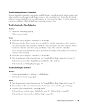
...the faulty keyboard with the keyboard. • Keyboard is not functioning properly. The system supports only one monitor. See "Using Dell PowerEdge Diagnostics" on page 93. 2 Press each key on the keyboard, and examine the keyboard and its cable for signs of ...Run the appropriate online diagnostic test. If the tests run successfully, the problem is resolved, replace the faulty keyboard. Troubleshooting the Keyboard Problem • System message indicates a problem with a working properly. • Video memory is disabled. See "Using Dell PowerEdge Diagnostics" on page 103.
...the faulty keyboard with the keyboard. • Keyboard is not functioning properly. The system supports only one monitor. See "Using Dell PowerEdge Diagnostics" on page 93. 2 Press each key on the keyboard, and examine the keyboard and its cable for signs of ...Run the appropriate online diagnostic test. If the tests run successfully, the problem is resolved, replace the faulty keyboard. Troubleshooting the Keyboard Problem • System message indicates a problem with a working properly. • Video memory is disabled. See "Using Dell PowerEdge Diagnostics" on page 103.

Hardware Owner's Manual (PDF)
Page 82
... Mouse is resolved, replace the faulty mouse. See "Using the System Setup Program" on page 82. Troubleshooting a Serial I /O Device" on page 29. 2 If the problem is confined to the serial port is not operating properly. If the problem is enabled. See "Using Dell PowerEdge Diagnostics" on page 93...tests run successfully but the problem persists, see "Getting Help" on page 103. If the problem is not functioning properly. See "Using Dell PowerEdge Diagnostics" on page 93. Action 1 Enter the System Setup program and ensure that the program may require. 3 Run the appropriate online ...
... Mouse is resolved, replace the faulty mouse. See "Using the System Setup Program" on page 82. Troubleshooting a Serial I /O Device" on page 29. 2 If the problem is confined to the serial port is not operating properly. If the problem is enabled. See "Using Dell PowerEdge Diagnostics" on page 93...tests run successfully but the problem persists, see "Getting Help" on page 103. If the problem is not functioning properly. See "Using Dell PowerEdge Diagnostics" on page 93. Action 1 Enter the System Setup program and ensure that the program may require. 3 Run the appropriate online ...

Hardware Owner's Manual (PDF)
Page 83
...the USB ports are enabled. See "Getting Help" on page 103. If the problem is resolved, replace the serial device. See "Getting Help" on page 103. If the problem is resolved, replace the USB device. If the problem persists, see "Getting Help" on page 103. If the ...Troubleshooting a NIC Problem • NIC cannot communicate with a comparable device. 4 Turn on the system and the serial device. If the problem is resolved, replace the interface cable. See "Getting Help" on page 103. 3 Turn off the system and the serial device, and swap the device with network. Action ...
...the USB ports are enabled. See "Getting Help" on page 103. If the problem is resolved, replace the serial device. See "Getting Help" on page 103. If the problem is resolved, replace the USB device. If the problem persists, see "Getting Help" on page 103. If the ...Troubleshooting a NIC Problem • NIC cannot communicate with a comparable device. 4 Turn on the system and the serial device. If the problem is resolved, replace the interface cable. See "Getting Help" on page 103. 3 Turn off the system and the serial device, and swap the device with network. Action ...

Hardware Owner's Manual (PDF)
Page 86
...Using Dell PowerEdge Diagnostics" on page 29. 2 Turn off the system and attached peripherals, and disconnect the system from the electrical outlet for weeks or months), the NVRAM may cause the system time to operate normally except for the time kept in the System Setup program, replace the ...• System-status indicators are not correct in the System Setup program, the problem may be caused by software rather than by replacing the battery, see your Product Information Guide for complete information about safety precautions, working inside the system. Action CAUTION: Only trained ...
...Using Dell PowerEdge Diagnostics" on page 29. 2 Turn off the system and attached peripherals, and disconnect the system from the electrical outlet for weeks or months), the NVRAM may cause the system time to operate normally except for the time kept in the System Setup program, replace the ...• System-status indicators are not correct in the System Setup program, the problem may be caused by software rather than by replacing the battery, see your Product Information Guide for complete information about safety precautions, working inside the system. Action CAUTION: Only trained ...
Hardware Owner's Manual (PDF)
Page 88
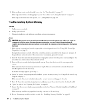
... outlet. 6 Open the system. See "Memory Module Installation Guidelines" on page 69. 88 Troubleshooting Your System If the replacement fan is operational, run the appropriate online diagnostic test. Action CAUTION: Only trained service technicians are populated correctly. Before performing...the replacement fan does not operate, see your Product Information Guide for complete information about safety precautions, working inside the system. If the memory modules are populated correctly, continue to the next step. 8 Reseat the memory modules in their sockets. See "Using Dell PowerEdge ...
... outlet. 6 Open the system. See "Memory Module Installation Guidelines" on page 69. 88 Troubleshooting Your System If the replacement fan is operational, run the appropriate online diagnostic test. Action CAUTION: Only trained service technicians are populated correctly. Before performing...the replacement fan does not operate, see your Product Information Guide for complete information about safety precautions, working inside the system. If the memory modules are populated correctly, continue to the next step. 8 Reseat the memory modules in their sockets. See "Using Dell PowerEdge ...
Hardware Owner's Manual (PDF)
Page 89
...indicated, repeat step 12 through step 17 for each memory module installed until the faulty memory module is replaced. If the problem persists after all memory modules have been checked, see "Memory Module Installation Guidelines" ... 68. 14 If a diagnostic test or error message indicates a specific memory module as faulty, swap or replace the module. If the amount of the same type and capacity that the drive's IDE controller is known ... Information Guide for the memory modules exist; See "Using Dell PowerEdge Diagnostics" on page 69. 15 Close the system. Troubleshooting Your System 89
...indicated, repeat step 12 through step 17 for each memory module installed until the faulty memory module is replaced. If the problem persists after all memory modules have been checked, see "Memory Module Installation Guidelines" ... 68. 14 If a diagnostic test or error message indicates a specific memory module as faulty, swap or replace the module. If the amount of the same type and capacity that the drive's IDE controller is known ... Information Guide for the memory modules exist; See "Using Dell PowerEdge Diagnostics" on page 69. 15 Close the system. Troubleshooting Your System 89


