Getting Started Guide
Page 6
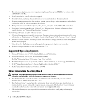
.... • Serial connector for console redirection support. • Security features, including chassis-intrusion detection and keylock on the optional bezel. • Systems management circuitry that came with your system or on support.dell.com. • CDs included with your system: • A System Setup program for quickly viewing and changing system configuration information...
.... • Serial connector for console redirection support. • Security features, including chassis-intrusion detection and keylock on the optional bezel. • Systems management circuitry that came with your system or on support.dell.com. • CDs included with your system: • A System Setup program for quickly viewing and changing system configuration information...

Getting Started Guide
Page 10
Turning on the System Turn on the system and the monitor. Installing the Bezel Install the bezel (optional). 8 Getting Started With Your System The power indicators should light. Press the power button on the system and monitor (optional). Adjust the monitor's controls until the displayed image is satisfactory.
Turning on the System Turn on the system and the monitor. Installing the Bezel Install the bezel (optional). 8 Getting Started With Your System The power indicators should light. Press the power button on the system and monitor (optional). Adjust the monitor's controls until the displayed image is satisfactory.
Getting Started Guide
Page 13
... SATA channels Video Video type Video memory Power AC power supply Wattage Voltage Maximum inrush current System battery Physical Height Width Depth With optional bezel Without optional bezel Weight (maximum configuration) 15-pin VGA Two 4-pin, USB 2.0 compliant 40 pin Two 7 pin Integrated ATI RN50 VGA controller 16 MB, 32MB when available...
... SATA channels Video Video type Video memory Power AC power supply Wattage Voltage Maximum inrush current System battery Physical Height Width Depth With optional bezel Without optional bezel Weight (maximum configuration) 15-pin VGA Two 4-pin, USB 2.0 compliant 40 pin Two 7 pin Integrated ATI RN50 VGA controller 16 MB, 32MB when available...
Hardware Owner's Manual (PDF)
Page 4
... Setup Module Options 41 3 Installing System Components 43 Recommended Tools 43 Inside the System 43 Opening and Closing the System 44 Removing the Bezel 45 Installing the Bezel 45 Opening the System 46 Closing the System 47 Cooling Shroud 47 Removing the Cooling Shroud 47 Installing the Cooling Shroud 48 System Battery...
... Setup Module Options 41 3 Installing System Components 43 Recommended Tools 43 Inside the System 43 Opening and Closing the System 44 Removing the Bezel 45 Installing the Bezel 45 Opening the System 46 Closing the System 47 Cooling Shroud 47 Removing the Cooling Shroud 47 Installing the Cooling Shroud 48 System Battery...

Hardware Owner's Manual (PDF)
Page 11
Front-Panel Features and Indicators 3 4 2 5 1 12 11 10 9 6 7 8 About Your System 11 See "Opening the System" on the system front panel behind the optional bezel. (To remove the bezel, press the latch at the left end of the bezel. Figure 1-1. Front-Panel Features and Indicators Figure 1-1 shows the controls, indicators, connectors, and features on page 46.) Table 1-2 provides component descriptions.
Front-Panel Features and Indicators 3 4 2 5 1 12 11 10 9 6 7 8 About Your System 11 See "Opening the System" on the system front panel behind the optional bezel. (To remove the bezel, press the latch at the left end of the bezel. Figure 1-1. Front-Panel Features and Indicators Figure 1-1 shows the controls, indicators, connectors, and features on page 46.) Table 1-2 provides component descriptions.

Hardware Owner's Manual (PDF)
Page 13
... directed to a system problem. Front-Panel Components (continued) Item Component Icon 6 System status indicator 7 System identification button 8 Hard drive 1 9 Hard drive 0 10 Optical drive 11 Bezel 12 NMI button Description The blue system status indicator lights up during normal system operation. When one of a paper clip. Optional. About Your System 13...
... directed to a system problem. Front-Panel Components (continued) Item Component Icon 6 System status indicator 7 System identification button 8 Hard drive 1 9 Hard drive 0 10 Optical drive 11 Bezel 12 NMI button Description The blue system status indicator lights up during normal system operation. When one of a paper clip. Optional. About Your System 13...
Hardware Owner's Manual (PDF)
Page 43
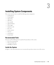
... perform the procedures in this section: • Key to the system keylock • Wrist grounding strap • #2 Phillips screwdriver Inside the System In Figure 3-1, the bezel and system cover are removed to provide an interior view of the system. Installing System Components 43
... perform the procedures in this section: • Key to the system keylock • Wrist grounding strap • #2 Phillips screwdriver Inside the System In Figure 3-1, the bezel and system cover are removed to provide an interior view of the system. Installing System Components 43
Hardware Owner's Manual (PDF)
Page 44
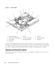
Using a riser card, the system can accommodate two expansion cards. Power is enclosed by an optional bezel and cover. Figure 3-1. The processor and memory are installed directly on the system board. The peripheral bays provide space for up to the system board ...and drives through one nonredundant power supply. To upgrade or troubleshoot the system, remove the bezel and cover. 44 Installing System Components Opening and Closing the System The system is supplied to two hard drives and an optional optical drive. Inside...
Using a riser card, the system can accommodate two expansion cards. Power is enclosed by an optional bezel and cover. Figure 3-1. The processor and memory are installed directly on the system board. The peripheral bays provide space for up to the system board ...and drives through one nonredundant power supply. To upgrade or troubleshoot the system, remove the bezel and cover. 44 Installing System Components Opening and Closing the System The system is supplied to two hard drives and an optional optical drive. Inside...

Hardware Owner's Manual (PDF)
Page 45
Removing the Bezel 1 Unlock the bezel. Installing and Removing the Optional Bezel 1 2 1 key lock 2 bezel Installing the Bezel 1 Hook the right end of the bezel into the bezel slot on the right side of the system front plate 2 Rotate the other end of the bezel and pull the bezel away from the front panel. 3 Unhook the right end of the bezel toward the front panel and press the bezel onto the panel to engage the latch. 3 Lock the bezel. Figure 3-2. See Figure 3-2. 2 Unlatch the left end of the bezel and rotate it away from the system. Installing System Components 45
Removing the Bezel 1 Unlock the bezel. Installing and Removing the Optional Bezel 1 2 1 key lock 2 bezel Installing the Bezel 1 Hook the right end of the bezel into the bezel slot on the right side of the system front plate 2 Rotate the other end of the bezel and pull the bezel away from the front panel. 3 Unhook the right end of the bezel toward the front panel and press the bezel onto the panel to engage the latch. 3 Lock the bezel. Figure 3-2. See Figure 3-2. 2 Unlatch the left end of the bezel and rotate it away from the system. Installing System Components 45

Hardware Owner's Manual (PDF)
Page 137
... passwords, 38 B Baseboard Management Controller (BMC), 40 battery removing or replacing, 49 replacing, 49 troubleshooting, 86 beep codes, 24 bezel installing, 45 removing, 45 C CD drive installing, 51 removing, 50 troubleshooting, 89 checking equipment, 80 configuring the boot drive,... 47 opening, 46 CPU Information screen, 33 D damaged systems troubleshooting, 85 Dell contacting, 108 Dell PowerEdge Diagnostics using, 93 diagnostics advanced testing options, 95 running from the utility partition, 94 using Dell PowerEdge Diagnostics, 93 when to use, 94 diagnostics indicator codes, 22 drives CD,...
... passwords, 38 B Baseboard Management Controller (BMC), 40 battery removing or replacing, 49 replacing, 49 troubleshooting, 86 beep codes, 24 bezel installing, 45 removing, 45 C CD drive installing, 51 removing, 50 troubleshooting, 89 checking equipment, 80 configuring the boot drive,... 47 opening, 46 CPU Information screen, 33 D damaged systems troubleshooting, 85 Dell contacting, 108 Dell PowerEdge Diagnostics using, 93 diagnostics advanced testing options, 95 running from the utility partition, 94 using Dell PowerEdge Diagnostics, 93 when to use, 94 diagnostics indicator codes, 22 drives CD,...

Hardware Owner's Manual (PDF)
Page 138
H hard drives configuring the boot drive, 52 installing, 56 removing, 52 troubleshooting, 90 I indicators back-panel, 14 front-panel, 11 NIC, 15 installing bezel, 45 CD drive, 51 control panel, 74 cooling shroud, 48 expansion cards, 63 hard drives, 56 memory modules, 69 optical drive, 51 PCI fan assembly, ...
H hard drives configuring the boot drive, 52 installing, 56 removing, 52 troubleshooting, 90 I indicators back-panel, 14 front-panel, 11 NIC, 15 installing bezel, 45 CD drive, 51 control panel, 74 cooling shroud, 48 expansion cards, 63 hard drives, 56 memory modules, 69 optical drive, 51 PCI fan assembly, ...

Hardware Owner's Manual (PDF)
Page 139
...serial I/O device troubleshooting, 82 setup password assigning, 39 changing, 40 features, 37 working with, 40 startup accessing system features, 10 support contacting Dell, 108 system battery replacing, 49 troubleshooting, 86 system board connectors, 98 installing, 76 jumpers, 97 removing, 75 system cooling troubleshooting, 87 system..., 82 start-up routine, 79 system cooling, 87 USB device, 83 video, 81 wet system, 84 Index 139 recommended tools, 43 removing bezel, 45 CD drive, 50 control panel, 73 cooling shroud, 47 expansion cards, 65 hard drives, 52 memory modules, 70 optical drive, 50...
...serial I/O device troubleshooting, 82 setup password assigning, 39 changing, 40 features, 37 working with, 40 startup accessing system features, 10 support contacting Dell, 108 system battery replacing, 49 troubleshooting, 86 system board connectors, 98 installing, 76 jumpers, 97 removing, 75 system cooling troubleshooting, 87 system..., 82 start-up routine, 79 system cooling, 87 USB device, 83 video, 81 wet system, 84 Index 139 recommended tools, 43 removing bezel, 45 CD drive, 50 control panel, 73 cooling shroud, 47 expansion cards, 65 hard drives, 52 memory modules, 70 optical drive, 50...

Rack Installation Guide
Page 16
... (4 per mounting rail) front of rack rails modules (2) Installing and Removing Chassis Static Rail Modules NOTE: You do not need to remove the optional front bezel to the front of the chassis toward the front and midpoint (see Figure 1-7). 3 To seat the rails, pull up on the front latches attached to...
... (4 per mounting rail) front of rack rails modules (2) Installing and Removing Chassis Static Rail Modules NOTE: You do not need to remove the optional front bezel to the front of the chassis toward the front and midpoint (see Figure 1-7). 3 To seat the rails, pull up on the front latches attached to...

Rack Installation Guide
Page 20
... System From the Rack To remove the system from the rack, perform the following procedure: NOTE: You do not need to remove the optional front bezel to install or remove the system from the rack. 1 Turn off the system and attached peripherals, and disconnect the system from the electrical outlet. 2 Disengage...
... System From the Rack To remove the system from the rack, perform the following procedure: NOTE: You do not need to remove the optional front bezel to install or remove the system from the rack. 1 Turn off the system and attached peripherals, and disconnect the system from the electrical outlet. 2 Disengage...


