

Installing a SATA Optical Drive
Page 5
...Installing a SATA Optical Drive 5 Figure 1-1. Replacing the Optical Drive in a PowerEdge 2950 or 2970 System 2 1 3 4 5 6 7 1 optical drive 3 interposer 5 SATA power cable 7 optical drive carrier 2 interposer release latch 4 SATA cable 6 carrier latch Replacing a PowerEdge 1950 Optical Drive NOTE: The replacement drive tray provided in the installation kit ... the side of the SATA optical drive into the tray until the pins on the carrier align with PowerEdge 1950 systems. If you are replacing an existing optical drive, do not reuse the interposer board attached to the tray....
...Installing a SATA Optical Drive 5 Figure 1-1. Replacing the Optical Drive in a PowerEdge 2950 or 2970 System 2 1 3 4 5 6 7 1 optical drive 3 interposer 5 SATA power cable 7 optical drive carrier 2 interposer release latch 4 SATA cable 6 carrier latch Replacing a PowerEdge 1950 Optical Drive NOTE: The replacement drive tray provided in the installation kit ... the side of the SATA optical drive into the tray until the pins on the carrier align with PowerEdge 1950 systems. If you are replacing an existing optical drive, do not reuse the interposer board attached to the tray....

Getting Started Guide
Page 8
Installing the Rails and System in a Rack Once you need them later. See your rack installation documentation for your system, install the rails and the system in the rack. Keep all shipping materials in case you have read the "Safety Instructions" located in the rack installation documentation for instructions on installing your system and identify each item. Unpacking the System Unpack your system in a rack. 6 Getting Started With Your System
Installing the Rails and System in a Rack Once you need them later. See your rack installation documentation for your system, install the rails and the system in the rack. Keep all shipping materials in case you have read the "Safety Instructions" located in the rack installation documentation for instructions on installing your system and identify each item. Unpacking the System Unpack your system in a rack. 6 Getting Started With Your System

Hardware Owner's Manual (PDF)
Page 58
...card. c Close the handle to lock the drive in place. 4 Replace the front bezel, if it was removed in the carrier rail. 2 Remove the four screws from the slide rails on the left end of the slots in step 1. Replacing a Hard-Drive Carrier Removing a Hard Drive From a Hard-Drive Carrier.... c Rotate the left end away from the rear, locate the release lever on the hard-drive carrier and separate the hard drive from the carrier rail to release the connector. Installing a Hot-Plug Hard Drive 1 2 3 1 hard drive 2 drive carrier 3 drive carrier release handle b Insert the hard-drive ...
...card. c Close the handle to lock the drive in place. 4 Replace the front bezel, if it was removed in the carrier rail. 2 Remove the four screws from the slide rails on the left end of the slots in step 1. Replacing a Hard-Drive Carrier Removing a Hard Drive From a Hard-Drive Carrier.... c Rotate the left end away from the rear, locate the release lever on the hard-drive carrier and separate the hard drive from the carrier rail to release the connector. Installing a Hot-Plug Hard Drive 1 2 3 1 hard drive 2 drive carrier 3 drive carrier release handle b Insert the hard-drive ...

Hardware Owner's Manual (PDF)
Page 61
... the hard-drive carrier. When aligned correctly, the rear of the interposer will be flush with the hole labeled "SATAu" on the inside top carrier rail so that the tabs on the interposer card bracket attach to the slots on the hard drive carrier. See Figure 3-7. 4 Attach the interposer card to... until the latch on the card bracket clicks into the inside of the card to seat the connector. c Push the bottom end of the carrier rail.
... the hard-drive carrier. When aligned correctly, the rear of the interposer will be flush with the hole labeled "SATAu" on the inside top carrier rail so that the tabs on the interposer card bracket attach to the slots on the hard drive carrier. See Figure 3-7. 4 Attach the interposer card to... until the latch on the card bracket clicks into the inside of the card to seat the connector. c Push the bottom end of the carrier rail.

Hardware Owner's Manual (PDF)
Page 84
... electrical outlet. 2 Remove the front bezel, if attached. See your Product Information Guide for the location of the diskette drive carrier with the drive bay rails in the media bay. b Push the carrier toward the system front plate until the plastic latch on the carrier locks into the system: a Align the...
... electrical outlet. 2 Remove the front bezel, if attached. See your Product Information Guide for the location of the diskette drive carrier with the drive bay rails in the media bay. b Push the carrier toward the system front plate until the plastic latch on the carrier locks into the system: a Align the...

Hardware Owner's Manual (PDF)
Page 86
... forward, sliding the carrier gently from the bay. See Figure 3-24. Removing and Installing the Tape Drive Carrier 1 4 3 2 1 tape drive blank 4 media bay 2 tape drive rails 3 release tab (2) 3 Remove the four screws affixing the tape drive blank to configure and install an internal SCSI tape drive. See Figure 3-25. 86 Installing...
... forward, sliding the carrier gently from the bay. See Figure 3-24. Removing and Installing the Tape Drive Carrier 1 4 3 2 1 tape drive blank 4 media bay 2 tape drive rails 3 release tab (2) 3 Remove the four screws affixing the tape drive blank to configure and install an internal SCSI tape drive. See Figure 3-25. 86 Installing...
Hardware Owner's Manual (PDF)
Page 87
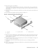
...See Figure 6-4 or Figure 6-5 for installation. Removing and Installing an Internal SCSI Tape Drive 1 2 3 4 1 screws (4) 4 tape drive 2 tape drive rails (2) 3 rail release tabs (2) 7 Route the tape drive's SCSI interface cable through the tape drive cable retention bracket and connect it to the connector on the backplane...as instructed in the software documentation that came with the four screw holes on the tape drive rails, affix the rails to the drive. 6 Insert the tape drive along the rails in the drive documentation. 5 Aligning the four holes on the tape drive with the drive...
...See Figure 6-4 or Figure 6-5 for installation. Removing and Installing an Internal SCSI Tape Drive 1 2 3 4 1 screws (4) 4 tape drive 2 tape drive rails (2) 3 rail release tabs (2) 7 Route the tape drive's SCSI interface cable through the tape drive cable retention bracket and connect it to the connector on the backplane...as instructed in the software documentation that came with the four screw holes on the tape drive rails, affix the rails to the drive. 6 Insert the tape drive along the rails in the drive documentation. 5 Aligning the four holes on the tape drive with the drive...

Hardware Owner's Manual (PDF)
Page 99
.... See "Closing the System" on the riser board. Installing System Components 99 Replacing the Left Riser Board 3 4 5 2 1 1 riser release pin 4 riser securing tabs (6) 2 expansion-card rails 5 riser securing slots (6) 3 expansion-card cage Installing the Left Riser Board CAUTION: Only trained service technicians are fully inserted in the expansion-card cage so...
.... See "Closing the System" on the riser board. Installing System Components 99 Replacing the Left Riser Board 3 4 5 2 1 1 riser release pin 4 riser securing tabs (6) 2 expansion-card rails 5 riser securing slots (6) 3 expansion-card cage Installing the Left Riser Board CAUTION: Only trained service technicians are fully inserted in the expansion-card cage so...
Rack Installation Guide
Page 5
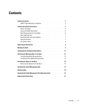
... Supplies 7 Rack Kit Contents 7 Installation Tasks 8 Removing the Rack Doors 9 Marking the Rack 9 Configuring the Sliding Rail Assemblies 11 Installing the Mounting Rails in the Rack 12 Installing RapidRails Mounting Rails 12 Installing the VersaRails Mounting Rails 13 Installing the System in the Rack 15 Removing the System From the Rack 16 Installing the...
... Supplies 7 Rack Kit Contents 7 Installation Tasks 8 Removing the Rack Doors 9 Marking the Rack 9 Configuring the Sliding Rail Assemblies 11 Installing the Mounting Rails in the Rack 12 Installing RapidRails Mounting Rails 12 Installing the VersaRails Mounting Rails 13 Installing the System in the Rack 15 Removing the System From the Rack 16 Installing the...

Rack Installation Guide
Page 7
... and side stabilizers on a single rack or front stabilizers for joined multiple racks before extending a component from potential damage. the slide rails can pinch your fingers. • Do not overload the AC supply branch circuit that the rack is safety-certified as a free-...slide assemblies at one extended component could cause the rack to tip over and may result in bodily injury under certain circumstances. Dell disclaims all applicable safety standards and local electric code requirements. Failure to install stabilizers accordingly before installing components in a rack. ...
... and side stabilizers on a single rack or front stabilizers for joined multiple racks before extending a component from potential damage. the slide rails can pinch your fingers. • Do not overload the AC supply branch circuit that the rack is safety-certified as a free-...slide assemblies at one extended component could cause the rack to tip over and may result in bodily injury under certain circumstances. Dell disclaims all applicable safety standards and local electric code requirements. Failure to install stabilizers accordingly before installing components in a rack. ...
Rack Installation Guide
Page 10
... the following tasks (described in detail in subsequent sections) in their numbered order: 1 Removing the rack doors 2 Marking the rack 3 Configuring the sliding rail assemblies 4 Installing the mounting rails in the rack • RapidRails installation • VersaRails installation 5 Installing the system in the rack 6 Installing the cable-management arm 7 Routing cables 8 Attaching...
... the following tasks (described in detail in subsequent sections) in their numbered order: 1 Removing the rack doors 2 Marking the rack 3 Configuring the sliding rail assemblies 4 Installing the mounting rails in the rack • RapidRails installation • VersaRails installation 5 Installing the system in the rack 6 Installing the cable-management arm 7 Routing cables 8 Attaching...

Rack Installation Guide
Page 11
... hole spacing (beginning at the top hole of a 1-U space) of the rack cabinet doors, never attempt to mark or place tape on the rack's vertical rail. Figure 1-2. Rack Installation Guide 9 CAUTION: Because of the size and weight of 15.9 mm, 15.9 mm, and 12.7 mm (0.625 inch, 0.625 inch, and 0.5 ... mm (0.5 inch) 15.9 mm (0.625 inch) 15.9 mm (0.625 inch) 12.7 mm (0.5 inch) CAUTION: If you are installing more than one system, install the mounting rails so that meet EIA-310 standards have round or square holes. If you want, you can make a note of vertical space for the front and...
... hole spacing (beginning at the top hole of a 1-U space) of the rack cabinet doors, never attempt to mark or place tape on the rack's vertical rail. Figure 1-2. Rack Installation Guide 9 CAUTION: Because of the size and weight of 15.9 mm, 15.9 mm, and 12.7 mm (0.625 inch, 0.625 inch, and 0.5 ... mm (0.5 inch) 15.9 mm (0.625 inch) 15.9 mm (0.625 inch) 12.7 mm (0.5 inch) CAUTION: If you are installing more than one system, install the mounting rails so that meet EIA-310 standards have round or square holes. If you want, you can make a note of vertical space for the front and...

Rack Installation Guide
Page 12
...the top hole). To mark the rack, perform the following steps: 1 Place a mark (or tape) on the rack's front vertical rails where you want to locate the bottom of the system you are installing in a rack that meets EIA-310 standards) and mark the rack...'s front vertical rails with a felt-tipped pen or masking tape (if you made (or count up three holes in the rack. This mark ... 1-U space is at the middle of tape indicates where the system's upper edge will be located on vertical rail (2)
...the top hole). To mark the rack, perform the following steps: 1 Place a mark (or tape) on the rack's front vertical rails where you want to locate the bottom of the system you are installing in a rack that meets EIA-310 standards) and mark the rack...'s front vertical rails with a felt-tipped pen or masking tape (if you made (or count up three holes in the rack. This mark ... 1-U space is at the middle of tape indicates where the system's upper edge will be located on vertical rail (2)

Rack Installation Guide
Page 13
...blue lever on the rotating mounting bracket (see Figure 1-4). 2 Rotate the bracket and slide it to the vertical rail. Changing the Position of the bracket determines whether the rail assembly is used as a RapidRail or a VersaRail. The position of the Rotating Mounting Bracket 1 2 5 ... 4 shoulder standoffs (2) 2 rotating bracket 5 notches (2) 3 release lever Rack Installation Guide 11 The RapidRail side of the rail. Configuring the Sliding Rail Assemblies The sliding rail assembly has a rotating mounting bracket at each end of the bracket has a hook and a latch that secure it to ...
...blue lever on the rotating mounting bracket (see Figure 1-4). 2 Rotate the bracket and slide it to the vertical rail. Changing the Position of the bracket determines whether the rail assembly is used as a RapidRail or a VersaRail. The position of the Rotating Mounting Bracket 1 2 5 ... 4 shoulder standoffs (2) 2 rotating bracket 5 notches (2) 3 release lever Rack Installation Guide 11 The RapidRail side of the rail. Configuring the Sliding Rail Assemblies The sliding rail assembly has a rotating mounting bracket at each end of the bracket has a hook and a latch that secure it to ...

Rack Installation Guide
Page 14
... flange should enter the top hole between the marks or tape you made on the slide assemblies are in the RapidRail configuration. Installing the Mounting Rails in the Rack Installing RapidRails Mounting Rails NOTE: Ensure that its mounting-bracket flange fits between the marks you placed (or numbered locations) on the vertical...
... flange should enter the top hole between the marks or tape you made on the slide assemblies are in the RapidRail configuration. Installing the Mounting Rails in the Rack Installing RapidRails Mounting Rails NOTE: Ensure that its mounting-bracket flange fits between the marks you placed (or numbered locations) on the vertical...

Rack Installation Guide
Page 15
...hooks seat and the push button pops out and clicks (see Figure 1-6). The three holes on the front of the rack. 2 Push the mounting rail forward until the mounting hooks enter their square holes, and then push down on the flange until the mounting hooks seat and the push button... with their square holes, and then push down on the mounting-bracket flange until the mounting hooks enter their respective holes on the back vertical rail. 4 Install two 10-32 x 0.5-inch flange-head Phillips screws in the upper and lower holes in the VersaRail configuration. See Figure 1-6. 1 At the ...
...hooks seat and the push button pops out and clicks (see Figure 1-6). The three holes on the front of the rack. 2 Push the mounting rail forward until the mounting hooks enter their square holes, and then push down on the flange until the mounting hooks seat and the push button... with their square holes, and then push down on the mounting-bracket flange until the mounting hooks enter their respective holes on the back vertical rail. 4 Install two 10-32 x 0.5-inch flange-head Phillips screws in the upper and lower holes in the VersaRail configuration. See Figure 1-6. 1 At the ...

Rack Installation Guide
Page 16
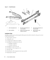
Figure 1-6. Installing VersaRails Mounting Rails 1 2 3 front of rack 1 mounting-bracket flange 2 10-32 x 0.5-inch flange-head Phillips screws (4 per mounting rail) 3 mounting rails (2) 14 Rack Installation Guide
Figure 1-6. Installing VersaRails Mounting Rails 1 2 3 front of rack 1 mounting-bracket flange 2 10-32 x 0.5-inch flange-head Phillips screws (4 per mounting rail) 3 mounting rails (2) 14 Rack Installation Guide
Rack Installation Guide
Page 17
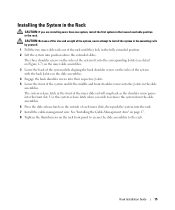
...Press the slide-release latch on the slide assemblies. 4 Engage the back shoulder screws into their respective J-slots. 5 Lower the front of the inner slide rail will snap back as the shoulder screw passes into position above the extended slides. CAUTION: Because of the size and weight of the system, never... attempt to install the system in the mounting rails by yourself. 1 Pull the two inner slide rails out of each inner slide, then push the system into the J-slots in the slide assemblies. Installing the System in ...
...Press the slide-release latch on the slide assemblies. 4 Engage the back shoulder screws into their respective J-slots. 5 Lower the front of the inner slide rail will snap back as the shoulder screw passes into position above the extended slides. CAUTION: Because of the size and weight of the system, never... attempt to install the system in the mounting rails by yourself. 1 Pull the two inner slide rails out of each inner slide, then push the system into the J-slots in the slide assemblies. Installing the System in ...

Rack Installation Guide
Page 19
... arm. 1 Fit the latch on the front end of the cable-management arm onto the bracket on the end of the mounting rail until the latch clicks (see Figure 1-7) and slide the system forward. 6 Pull the system completely out of the rack. Figure ...1-8. Installing the Cable-Management Arm 1 2 3 back of system 1 mounting rails (2) 3 latches (2) 4 2 brackets (2) 4 cable-management arm Rack Installation Guide 17 Installing the Cable-Management Arm NOTE: You can attach the cable-management arm...
... arm. 1 Fit the latch on the front end of the cable-management arm onto the bracket on the end of the mounting rail until the latch clicks (see Figure 1-7) and slide the system forward. 6 Pull the system completely out of the rack. Figure ...1-8. Installing the Cable-Management Arm 1 2 3 back of system 1 mounting rails (2) 3 latches (2) 4 2 brackets (2) 4 cable-management arm Rack Installation Guide 17 Installing the Cable-Management Arm NOTE: You can attach the cable-management arm...


