
Information Update
Page 11
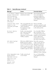
...device See see "Troubleshooting System Expansion Cards" in the Hardware Owner's Manual for information on setting the order of boot devices. controller slot. installed expansion card(s). Invalid PCIe card found in the Hardware Owner's Manual. No boot device available Faulty or missing optical drive ...subsystem, hard drive, or hard-drive subsystem, or no bootable USB key installed. PCI BIOS failed to loose; See "Installing a RAC Card" in the dedicated slot. Use a bootable USB key, CD, or hard drive. PCIe Degraded Link Faulty system board Width Error...
...device See see "Troubleshooting System Expansion Cards" in the Hardware Owner's Manual for information on setting the order of boot devices. controller slot. installed expansion card(s). Invalid PCIe card found in the Hardware Owner's Manual. No boot device available Faulty or missing optical drive ...subsystem, hard drive, or hard-drive subsystem, or no bootable USB key installed. PCI BIOS failed to loose; See "Installing a RAC Card" in the dedicated slot. Use a bootable USB key, CD, or hard drive. PCIe Degraded Link Faulty system board Width Error...
Information Update
Page 16
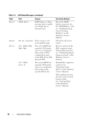
...PCIe expansion cards. Table 1-2. The system BIOS has reported a PCI parity error on a component that resides in PCI configuration space at bus ##, device ##, function ##. E1625 E1711 PS AC Current PCI PERR B## D## F## PCI PERR Slot # Power source is faulty. Corrective Actions Reseat the RAID ...Card Risers" in the Hardware Owner's Manual. 16 Information Update The system BIOS has reported a PCI parity error on a component that resides in the specified PCIe slot. If the problem persists, see "Troubleshooting System Cooling Problems" in the Hardware Owner's Manual....
...PCIe expansion cards. Table 1-2. The system BIOS has reported a PCI parity error on a component that resides in PCI configuration space at bus ##, device ##, function ##. E1625 E1711 PS AC Current PCI PERR B## D## F## PCI PERR Slot # Power source is faulty. Corrective Actions Reseat the RAID ...Card Risers" in the Hardware Owner's Manual. 16 Information Update The system BIOS has reported a PCI parity error on a component that resides in the specified PCIe slot. If the problem persists, see "Troubleshooting System Cooling Problems" in the Hardware Owner's Manual....
Information Update
Page 17
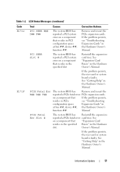
... Fatal Err B## D## F## The system BIOS has Remove and reseat the reported a PCIe fatal error PCIe expansion cards. PCI SERR Slot # The system BIOS has reported a PCI system error on a component that resides in the Hardware slot. If the problem persists, the riser card or system board is faulty. Remove and reseat the PCIe expansion...
... Fatal Err B## D## F## The system BIOS has Remove and reseat the reported a PCIe fatal error PCIe expansion cards. PCI SERR Slot # The system BIOS has reported a PCI system error on a component that resides in the Hardware slot. If the problem persists, the riser card or system board is faulty. Remove and reseat the PCIe expansion...

Information Update
Page 34
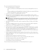
表 1-1 信息 原因 纠正措施 PCI BIOS failed to install 在 shadowing PCIe 设备 BIOS (选项 ROM)校验 和故障。... n PCIe Degraded Link 指定 PCIe Width Error: Integrated device Expected Link Width is n Actual Link Width is n PCIe Degraded Link Width Error: Slot n 故障。 Expected Link Width is n Actual Link Width is n PCIe Training Error: Embedded device 对于 SAS PCIe SAS 请&#...
表 1-1 信息 原因 纠正措施 PCI BIOS failed to install 在 shadowing PCIe 设备 BIOS (选项 ROM)校验 和故障。... n PCIe Degraded Link 指定 PCIe Width Error: Integrated device Expected Link Width is n Actual Link Width is n PCIe Degraded Link Width Error: Slot n 故障。 Expected Link Width is n Actual Link Width is n PCIe Training Error: Embedded device 对于 SAS PCIe SAS 请&#...
Getting Started Guide
Page 6
... including SAS 5/E, PERC 5/E, or PERC 4e/DC. true-color graphics are supported in cards). • A center riser card that has two full-length PCI-X 3.3-V, 64-bit,133-MHz slots on the back) capable of supporting a diskette drive, a CD-ROM drive, a keyboard, a mouse, or a USB flash drive. • Optional ... (capable of throttling back to support legacy PCI add-in the following left riser card that monitors operation of the system fans as well as critical system voltages and temperatures. See support.dell.com for system ID and error messaging. • System ID button on page 10. 4 ...
... including SAS 5/E, PERC 5/E, or PERC 4e/DC. true-color graphics are supported in cards). • A center riser card that has two full-length PCI-X 3.3-V, 64-bit,133-MHz slots on the back) capable of supporting a diskette drive, a CD-ROM drive, a keyboard, a mouse, or a USB flash drive. • Optional ... (capable of throttling back to support legacy PCI add-in the following left riser card that monitors operation of the system fans as well as critical system voltages and temperatures. See support.dell.com for system ID and error messaging. • System ID button on page 10. 4 ...

Getting Started Guide
Page 12
PCI-X, PCIe one half-height x8 lane 3.3-V (slot 1) two full-height, full-length 3.3-V, 64-bit, 133-MHz (slots 2 and 3) OR one full-height x8 lane 3.3-V (slot 2) and one fullheight x4 lane 3.3-V (slot 3) 533 or 667 (when available) MHz Fully Buffered DIMMs (FBD) eight 240-pin 256 MB, 512 MB, 1...1.44-MB external optional USB 3.5-inch, 1.44-MB Technical Specifications Processor Processor type Expansion Bus Bus type Expansion slots Center riser: PCIe Left riser PCI-X option: PCIe option: Memory Architecture Memory module sockets Memory module capacities Minimum RAM Maximum RAM Drives Hard drives ...
PCI-X, PCIe one half-height x8 lane 3.3-V (slot 1) two full-height, full-length 3.3-V, 64-bit, 133-MHz (slots 2 and 3) OR one full-height x8 lane 3.3-V (slot 2) and one fullheight x4 lane 3.3-V (slot 3) 533 or 667 (when available) MHz Fully Buffered DIMMs (FBD) eight 240-pin 256 MB, 512 MB, 1...1.44-MB external optional USB 3.5-inch, 1.44-MB Technical Specifications Processor Processor type Expansion Bus Bus type Expansion slots Center riser: PCIe Left riser PCI-X option: PCIe option: Memory Architecture Memory module sockets Memory module capacities Minimum RAM Maximum RAM Drives Hard drives ...

Hardware Owner's Manual (PDF)
Page 17
... System 17 Back-Panel Features and Indicators 1 2 3 4 13 12 11 10 9 87 6 5 1 center PCI riser (slot 1) 4 power supplies (2) 7 system status indicator connector 10 USB connectors (2) 13 remote access controller (optional) 2 left PCI riser (slot 2) 5 system identification button 8 NIC2 connector 3 left PCI riser (slot 3) 6 system status indicator 9 NIC1 connector 11 video connector 12 serial connector Connecting External...
... System 17 Back-Panel Features and Indicators 1 2 3 4 13 12 11 10 9 87 6 5 1 center PCI riser (slot 1) 4 power supplies (2) 7 system status indicator connector 10 USB connectors (2) 13 remote access controller (optional) 2 left PCI riser (slot 2) 5 system identification button 8 NIC2 connector 3 left PCI riser (slot 3) 6 system status indicator 9 NIC1 connector 11 video connector 12 serial connector Connecting External...

Hardware Owner's Manual (PDF)
Page 23
...see "Troubleshooting Expansion Cards" on a component that resides in the specified slot. If the problem that resides in the specified PCI slot. The system BIOS has reported a See "Expansion-Card Cage" on PCI system error on page 127. Unknown Err The system BIOS has determined ..., but is faulty. Table 1-6. LCD Status Messages (continued) Code E1711 E1712 E1714 E171F Text Causes Corrective Actions PCI PERR B## D## F## PCI PERR Slot # The system BIOS has reported a PCI parity error on page 147. Reinstall the expansion-card cage. See "Getting Help" on a component that hard ...
...see "Troubleshooting Expansion Cards" on a component that resides in the specified slot. If the problem that resides in the specified PCI slot. The system BIOS has reported a See "Expansion-Card Cage" on PCI system error on page 127. Unknown Err The system BIOS has determined ..., but is faulty. Table 1-6. LCD Status Messages (continued) Code E1711 E1712 E1714 E171F Text Causes Corrective Actions PCI PERR B## D## F## PCI PERR Slot # The system BIOS has reported a PCI parity error on page 147. Reinstall the expansion-card cage. See "Getting Help" on a component that hard ...

Hardware Owner's Manual (PDF)
Page 32
... sector on page 127. Remote configuration update attempt failed System unable to install PCI device BIOS (Option ROM) checksum failure is n Faulty or improperly installed PCIe card in the specified slot number. See "Expansion Cards" on page 76. Reseat the PCIe card in.... faulty system board. PCIe Training Error: Embedded Bus#nn/Dev#nn/Funcn PCIe Training Error: Slot n Faulty or improperly installed PCIe card in the specified slot number. PCI BIOS failed to process Remote Configuration request Retry Remote Configuration. 32 About Your System See "Troubleshooting ...
... sector on page 127. Remote configuration update attempt failed System unable to install PCI device BIOS (Option ROM) checksum failure is n Faulty or improperly installed PCIe card in the specified slot number. See "Expansion Cards" on page 76. Reseat the PCIe card in.... faulty system board. PCIe Training Error: Embedded Bus#nn/Dev#nn/Funcn PCIe Training Error: Slot n Faulty or improperly installed PCIe card in the specified slot number. PCI BIOS failed to process Remote Configuration request Retry Remote Configuration. 32 About Your System See "Troubleshooting ...
Hardware Owner's Manual (PDF)
Page 76
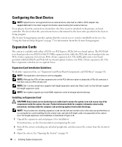
... See "Opening the System" on page 142. Configuring the Boot Device NOTE: System boot is illustrated in the System Setup program. See support.dell.com for installed boot devices. If you plan to boot the system from the electrical outlet. 3 Open the system. The device that the ...riser supports half-length expansion cards only. Expansion Cards The system is available with both PCI-X and PCIe left riser board provides one PCIe x8-lane expansion slot and one PCIe x8-lane expansion slot. NOTE: Slot 1 on page 37 for installing expansion cards into the central riser, and only half...
... See "Opening the System" on page 142. Configuring the Boot Device NOTE: System boot is illustrated in the System Setup program. See support.dell.com for installed boot devices. If you plan to boot the system from the electrical outlet. 3 Open the system. The device that the ...riser supports half-length expansion cards only. Expansion Cards The system is available with both PCI-X and PCIe left riser board provides one PCIe x8-lane expansion slot and one PCIe x8-lane expansion slot. NOTE: Slot 1 on page 37 for installing expansion cards into the central riser, and only half...

Hardware Owner's Manual (PDF)
Page 88
... the bracket clips with the 3.5" x4 and 2.5" x8 backplane configurations connects to the system board through an expansion card plugged into one of the PCI expansion card slots. Installing and Removing the Tape Drive Cable Retention Bracket 2 3 4 1 5 1 tape drive cable 4 bracket clips (6) 2 SCSI controller card 5 ...are fully engaged. Figure 3-26. Removing and Replacing the Tape Drive Cable Retention Bracket The optional tape drive available with their slots on the chassis wall, then slide the bracket toward the front of the system and disengaging the bracket from the chassis wall....
... the bracket clips with the 3.5" x4 and 2.5" x8 backplane configurations connects to the system board through an expansion card plugged into one of the PCI expansion card slots. Installing and Removing the Tape Drive Cable Retention Bracket 2 3 4 1 5 1 tape drive cable 4 bracket clips (6) 2 SCSI controller card 5 ...are fully engaged. Figure 3-26. Removing and Replacing the Tape Drive Cable Retention Bracket The optional tape drive available with their slots on the chassis wall, then slide the bracket toward the front of the system and disengaging the bracket from the chassis wall....

Hardware Owner's Manual (PDF)
Page 142
Sideplane Board Connectors 1 2 3 4 5 6 1 control panel (CTRL) 4 CD IDE (IDE) 2 SAS controller daughter card 3 chassis intrusion switch (PCIE_STORAGE) 5 pin guides (2) 6 system board connector Expansion-Card Riser-Board Components and PCI Buses Figure 6-7, Figure 6-8, and Figure 6-9 show the components on the sideplane board. Figure 6-6. Sideplane Board Connectors See Figure 6-6 for the location and description of connectors on the optional PCI-X/PCIe expansion-card riser boards, including the expansion-card slots and buses. 142 Jumpers and Connectors
Sideplane Board Connectors 1 2 3 4 5 6 1 control panel (CTRL) 4 CD IDE (IDE) 2 SAS controller daughter card 3 chassis intrusion switch (PCIE_STORAGE) 5 pin guides (2) 6 system board connector Expansion-Card Riser-Board Components and PCI Buses Figure 6-7, Figure 6-8, and Figure 6-9 show the components on the sideplane board. Figure 6-6. Sideplane Board Connectors See Figure 6-6 for the location and description of connectors on the optional PCI-X/PCIe expansion-card riser boards, including the expansion-card slots and buses. 142 Jumpers and Connectors

Hardware Owner's Manual (PDF)
Page 143
Figure 6-7. Optional PCI-X Left Expansion-Card Riser Board Components 1 2 3 slot 3 PCIe x4 lane width 3 1 riser release pin 4 pin guide (2) 5 2 slot 2 PCI-X 133-MHz 5 system board connector 4 3 slot 3 PCI-X 133-MHz Jumpers and Connectors 143 Optional PCIe Left Expansion-Card Riser Board Components 1 2 3 4 5 1 riser release pin 4 pin guide (2) 2 slot 2 PCIe x8 lane width 5 system board connector Figure 6-8.
Figure 6-7. Optional PCI-X Left Expansion-Card Riser Board Components 1 2 3 slot 3 PCIe x4 lane width 3 1 riser release pin 4 pin guide (2) 5 2 slot 2 PCI-X 133-MHz 5 system board connector 4 3 slot 3 PCI-X 133-MHz Jumpers and Connectors 143 Optional PCIe Left Expansion-Card Riser Board Components 1 2 3 4 5 1 riser release pin 4 pin guide (2) 2 slot 2 PCIe x8 lane width 5 system board connector Figure 6-8.

Hardware Owner's Manual (PDF)
Page 144
Optional PCIe Expansion-Card Central Riser Board Components 1 2 1 slot 1 PCI-X - NOTE: If you must install the jumper plug. See Figure 6-1 to their electrical outlets, and turn on page 54. 3 Lift up the memory module shroud. 4 ...
Optional PCIe Expansion-Card Central Riser Board Components 1 2 1 slot 1 PCI-X - NOTE: If you must install the jumper plug. See Figure 6-1 to their electrical outlets, and turn on page 54. 3 Lift up the memory module shroud. 4 ...

Hardware Owner's Manual (PDF)
Page 178
expansion slots PCI buses, 142 expansion-card cage removing, 78 replacing, 79 expansion-card riser board connectors, 142 PCI buses, 142 external devices connecting, 17 F fan bracket removing, 68 replacing, 69 features back-panel, 17 front-panel, 13 G guidelines expansion card installation, 76 guidelines ...
expansion slots PCI buses, 142 expansion-card cage removing, 78 replacing, 79 expansion-card riser board connectors, 142 PCI buses, 142 external devices connecting, 17 F fan bracket removing, 68 replacing, 69 features back-panel, 17 front-panel, 13 G guidelines expansion card installation, 76 guidelines ...


