
Rack- to-Tower Conversion Guide
Page 5
...Before You Begin 6 Installing the Tower-to-Rack Kit 7 Tower-to-Rack Kit Contents 7 Recommended Tools and Supplies 8 Conversion Tasks 8 Removing the Bezel, Metal Feet, and Cover 9 Removing the Control Panel Assembly and Tower Front Panel 12 Installing the Rack Front Panel and Control Panel Assembly 14 ...Cables 17 Installing the Rack Bezel 17 Installing the Rack Doors 18 Installing the Rack-to-Tower Kit 18 Rack-to-Tower Kit Contents 18 Before You Begin 20 Removing the Rack Doors 20 Recommended Tools and Supplies 20 Conversion Tasks 20 Removing the Rack Doors 20 Removing the...
...Before You Begin 6 Installing the Tower-to-Rack Kit 7 Tower-to-Rack Kit Contents 7 Recommended Tools and Supplies 8 Conversion Tasks 8 Removing the Bezel, Metal Feet, and Cover 9 Removing the Control Panel Assembly and Tower Front Panel 12 Installing the Rack Front Panel and Control Panel Assembly 14 ...Cables 17 Installing the Rack Bezel 17 Installing the Rack Doors 18 Installing the Rack-to-Tower Kit 18 Rack-to-Tower Kit Contents 18 Before You Begin 20 Removing the Rack Doors 20 Recommended Tools and Supplies 20 Conversion Tasks 20 Removing the Rack Doors 20 Removing the...

Rack- to-Tower Conversion Guide
Page 7
CAUTION: After installing system/components in a rack, never pull more than one component out of your responsibility to -Tower Conversion Guide 5 If you install the kit in bodily injury under certain circumstances. Therefore, always install the stabilizers before installing components in an approved rack by any safety agencies. The weight of more than one time...
CAUTION: After installing system/components in a rack, never pull more than one component out of your responsibility to -Tower Conversion Guide 5 If you install the kit in bodily injury under certain circumstances. Therefore, always install the stabilizers before installing components in an approved rack by any safety agencies. The weight of more than one time...

Rack- to-Tower Conversion Guide
Page 8
... without tools, and the VersaRails™ rack kit can be installed in most industry-standard rack cabinets. Instructions for additional information. The Dell™ RapidRails™ rack kit can be installed by trained service technicians in a rack that meets the specifications of cabinet control may result in damage to -Tower Conversion Guide NOTE: If your System Information document...
... without tools, and the VersaRails™ rack kit can be installed in most industry-standard rack cabinets. Instructions for additional information. The Dell™ RapidRails™ rack kit can be installed by trained service technicians in a rack that meets the specifications of cabinet control may result in damage to -Tower Conversion Guide NOTE: If your System Information document...

Rack- to-Tower Conversion Guide
Page 9
... for instructions on its slide assemblies at one system out of the rack with keylock, keys, and attaching hardware • Six 10-32 shoulder nuts • Rack control panel carrier assembly kit Tower-to-Rack and Rack-to-Tower Conversion Guide 7 CAUTION: You must strictly follow the procedures in this document to protect yourself as well...
... for instructions on its slide assemblies at one system out of the rack with keylock, keys, and attaching hardware • Six 10-32 shoulder nuts • Rack control panel carrier assembly kit Tower-to-Rack and Rack-to-Tower Conversion Guide 7 CAUTION: You must strictly follow the procedures in this document to protect yourself as well...
Rack- to-Tower Conversion Guide
Page 10
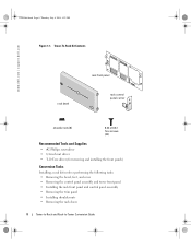
Tower-To-Rack Kit Contents www.dell.com | support.dell.com rack bezel rack front panel rack control panel carrier shoulder nuts (6) 6-32 x 0.312 Torx screws (22) Recommended Tools and Supplies • #2 Phillips screwdriver • 1/4-inch nut driver • T-10 Torx driver (for removing and installing the front panels) Conversion Tasks Installing a rack kit involves performing the following tasks: • Removing...
Tower-To-Rack Kit Contents www.dell.com | support.dell.com rack bezel rack front panel rack control panel carrier shoulder nuts (6) 6-32 x 0.312 Torx screws (22) Recommended Tools and Supplies • #2 Phillips screwdriver • 1/4-inch nut driver • T-10 Torx driver (for removing and installing the front panels) Conversion Tasks Installing a rack kit involves performing the following tasks: • Removing...

Rack- to-Tower Conversion Guide
Page 16
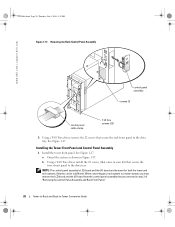
...and Front Panel screws (3) T-10 Torx screws (22) control panel assembly drive tray in Figure 1-6. Installing the Rack Front Panel and Control Panel Assembly 1 Install the rack front panel a Orient the system as shown in maintenance position front panel control panel cable clamp 3 Using a...T-10 Torx driver, install the 22 screws (that secure the rack front panel to -Tower Conversion Guide Y1001bk0.book Page 14 Thursday, July 8, 2004 4:32 PM www.dell.com | support.dell.com Figure 1-6. See Figure 1-6. When converting your kit) that came in step 2 of "Removing the Control Panel Assembly...
...and Front Panel screws (3) T-10 Torx screws (22) control panel assembly drive tray in Figure 1-6. Installing the Rack Front Panel and Control Panel Assembly 1 Install the rack front panel a Orient the system as shown in maintenance position front panel control panel cable clamp 3 Using a...T-10 Torx driver, install the 22 screws (that secure the rack front panel to -Tower Conversion Guide Y1001bk0.book Page 14 Thursday, July 8, 2004 4:32 PM www.dell.com | support.dell.com Figure 1-6. See Figure 1-6. When converting your kit) that came in step 2 of "Removing the Control Panel Assembly...

Rack- to-Tower Conversion Guide
Page 17
...7 Connect any cables to damage the system ID switch plunger. e Align the LCD board on the control panel assembly with your kit) that they were removed from the rack carrier plastic lens. See Figure 1-6. 4 Connect the control panel assembly cable to the SCSI backplane board. 5 Orient the system ... screws (that secures the drive tray release lever to -Tower Conversion Guide 15 NOTE: Ensure that secures the I /O board to the rack front panel. 3 Inside the drive tray, latch the control panel assembly cable clamp. Tower-to-Rack and Rack-to the drive tray. 10 Install the top cover. k ...
...7 Connect any cables to damage the system ID switch plunger. e Align the LCD board on the control panel assembly with your kit) that they were removed from the rack carrier plastic lens. See Figure 1-6. 4 Connect the control panel assembly cable to the SCSI backplane board. 5 Orient the system ... screws (that secures the drive tray release lever to -Tower Conversion Guide 15 NOTE: Ensure that secures the I /O board to the rack front panel. 3 Inside the drive tray, latch the control panel assembly cable clamp. Tower-to-Rack and Rack-to the drive tray. 10 Install the top cover. k ...

Rack- to-Tower Conversion Guide
Page 20
... Installing the Rack Bezel www.dell.com | support.dell.com keylock bezel release latch Installing the Rack Doors See the documentation provided with keylock and keys • One tower front panel 18 Tower-to-Rack and Rack-to -tower kit includes the ...following items (see Figure 1-10): • One tower bezel complete with the rack for instructions on installing rack doors. Rack-to-Tower Kit Contents The rack-to -Tower Conversion...
... Installing the Rack Bezel www.dell.com | support.dell.com keylock bezel release latch Installing the Rack Doors See the documentation provided with keylock and keys • One tower front panel 18 Tower-to-Rack and Rack-to -tower kit includes the ...following items (see Figure 1-10): • One tower bezel complete with the rack for instructions on installing rack doors. Rack-to-Tower Kit Contents The rack-to -Tower Conversion...

Rack- to-Tower Conversion Guide
Page 21
Y1001bk0.book Page 19 Thursday, July 8, 2004 4:32 PM • One painted top cover • One tower trim panel • Tower control panel carrier assembly kit • Twenty-two 6-32 x 0.312-inch black flat-head Torx screws Figure 1-10. Rack-to-Tower Kit Contents tower cover tower trim panel tower front panel tower bezel metal feet (4) tower control panel carrier 8-32 x 0.312 6-32 x 0.312 hex-head Torx screws screws (4) (22) Tower-to-Rack and Rack-to-Tower Conversion Guide 19
Y1001bk0.book Page 19 Thursday, July 8, 2004 4:32 PM • One painted top cover • One tower trim panel • Tower control panel carrier assembly kit • Twenty-two 6-32 x 0.312-inch black flat-head Torx screws Figure 1-10. Rack-to-Tower Kit Contents tower cover tower trim panel tower front panel tower bezel metal feet (4) tower control panel carrier 8-32 x 0.312 6-32 x 0.312 hex-head Torx screws screws (4) (22) Tower-to-Rack and Rack-to-Tower Conversion Guide 19

Rack- to-Tower Conversion Guide
Page 22
Y1001bk0.book Page 20 Thursday, July 8, 2004 4:32 PM www.dell.com | support.dell.com Before You Begin Before you begin removing your rack cabinet. Recommended Tools and Supplies The following tools are required to perform the conversion: • #2 Phillips screwdriver • 1/4-inch nut driver • Torx T-10...prevent damage to the doors while removing the system and its rack kit from the rack cabinet to provide access to a tower version system, carefully read "Safety Instructions." Next, remove the cable tray from the rack and converting it to the interior of the cable tray. ...
Y1001bk0.book Page 20 Thursday, July 8, 2004 4:32 PM www.dell.com | support.dell.com Before You Begin Before you begin removing your rack cabinet. Recommended Tools and Supplies The following tools are required to perform the conversion: • #2 Phillips screwdriver • 1/4-inch nut driver • Torx T-10...prevent damage to the doors while removing the system and its rack kit from the rack cabinet to provide access to a tower version system, carefully read "Safety Instructions." Next, remove the cable tray from the rack and converting it to the interior of the cable tray. ...
Rack- to-Tower Conversion Guide
Page 30
...: The control panel assembly's LCD board and the I /O board from the control panel assembly that came in your rack system to -Tower Conversion Guide Removing the Rack Control Panel Assembly www.dell.com | support.dell.com control panel assembly screws (2) control panel cable clamp T-10 Torx screws (22) 3 Using a T-10 Torx...1-17 Installing the Tower Front Panel and Control Panel Assembly 1 Install the tower front panel. See Figure 1-17. When converting your kit) that secure the rack front panel to the drive tray. Y1001bk0.book Page 28 Thursday, July 8, 2004 4:32 PM Figure 1-17.
...: The control panel assembly's LCD board and the I /O board from the control panel assembly that came in your rack system to -Tower Conversion Guide Removing the Rack Control Panel Assembly www.dell.com | support.dell.com control panel assembly screws (2) control panel cable clamp T-10 Torx screws (22) 3 Using a T-10 Torx...1-17 Installing the Tower Front Panel and Control Panel Assembly 1 Install the tower front panel. See Figure 1-17. When converting your kit) that secure the rack front panel to the drive tray. Y1001bk0.book Page 28 Thursday, July 8, 2004 4:32 PM Figure 1-17.

Rack- to-Tower Conversion Guide
Page 31
...the LCD board to the rack carrier. i Align the tabs on the control panel assembly with your kit. The devices should be ...careful not to damage the system ID switch plunger. See Figure 1-18. b Using a #2 Phillips screwdriver, remove the two screws that secures the I/O board to the rack... in place, install the three screws (that came with your kit) that the system is slightly hanging over the edge. Y1001bk0....NOTE: Ensure that they were removed from the rack carrier plastic lens. NOTICE: The system ID...-to-Rack and Rack-to the drive tray. 10 Install the...
...the LCD board to the rack carrier. i Align the tabs on the control panel assembly with your kit. The devices should be ...careful not to damage the system ID switch plunger. See Figure 1-18. b Using a #2 Phillips screwdriver, remove the two screws that secures the I/O board to the rack... in place, install the three screws (that came with your kit) that the system is slightly hanging over the edge. Y1001bk0....NOTE: Ensure that they were removed from the rack carrier plastic lens. NOTICE: The system ID...-to-Rack and Rack-to the drive tray. 10 Install the...

Rack- to-Tower Conversion Guide
Page 32
... feet (4) flat working surface hex-head Phillips screws (4) 4 Orient the system as shown in each corner and secure the foot with the metal foot kit. www.dell.com | support.dell.com Y1001bk0.book Page 30 Thursday, July 8, 2004 4:32 PM 2 Insert the two tabs on the metal foot into the slots on the..., then fit the free end of the bezel onto the system. See Figure 1-18. Figure 1-18. Secure the bezel with the keylock. 30 Tower-to-Rack and Rack-to-Tower Conversion Guide
... feet (4) flat working surface hex-head Phillips screws (4) 4 Orient the system as shown in each corner and secure the foot with the metal foot kit. www.dell.com | support.dell.com Y1001bk0.book Page 30 Thursday, July 8, 2004 4:32 PM 2 Insert the two tabs on the metal foot into the slots on the..., then fit the free end of the bezel onto the system. See Figure 1-18. Figure 1-18. Secure the bezel with the keylock. 30 Tower-to-Rack and Rack-to-Tower Conversion Guide


