
Information Update
Page 9
...faulty system board. Check the SEL for details on the LCD. See "Troubleshooting Redundant Power Supplies" in your Installation and Troubleshooting Guide. faulty or improperly installed power supply; See "Installing the ExpansionCard Cage" in your Installation and Troubleshooting Guide. Information Update 7...E0212 E0212 E0212 E0412 Line 2 Message Causes Corrective Actions OVRFLW CHECK LOG LCD overflow message. VOLT PG n System power supply is out of three error messages can display sequentially on the events. Replace the RAID battery. VOLT BATT CMOS Faulty...
...faulty system board. Check the SEL for details on the LCD. See "Troubleshooting Redundant Power Supplies" in your Installation and Troubleshooting Guide. faulty or improperly installed power supply; See "Installing the ExpansionCard Cage" in your Installation and Troubleshooting Guide. Information Update 7...E0212 E0212 E0212 E0412 Line 2 Message Causes Corrective Actions OVRFLW CHECK LOG LCD overflow message. VOLT PG n System power supply is out of three error messages can display sequentially on the events. Replace the RAID battery. VOLT BATT CMOS Faulty...
Information Update
Page 10
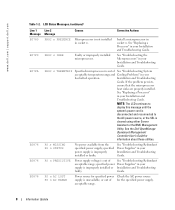
... out of See "Troubleshooting Redundant acceptable range; www.dell.com | support.dell.com Table 1-2. Install a microprocessor in your Installation and Troubleshooting Guide. See the Dell OpenManage Baseboard Management Controller User's Guide for specified power Check the AC power source supply is improperly installed or Installation and Troubleshooting faulty. specified power Power Supplies" in socket n. NOTE: The LCD continues to...
... out of See "Troubleshooting Redundant acceptable range; www.dell.com | support.dell.com Table 1-2. Install a microprocessor in your Installation and Troubleshooting Guide. See the Dell OpenManage Baseboard Management Controller User's Guide for specified power Check the AC power source supply is improperly installed or Installation and Troubleshooting faulty. specified power Power Supplies" in socket n. NOTE: The LCD continues to...

Information Update
Page 12
Installing the cable-management arm on the right side (when facing the back of the rack will require you to disengage the cablemanagement arm to access the power supplies for removal or replacement. 10 Information Update www.dell.com | support.dell.com Installing the Cable-Management Arm Although the cable-management arm can be installed on either side of the system rack, it is recommended that you install it on the left side of the system).
Installing the cable-management arm on the right side (when facing the back of the rack will require you to disengage the cablemanagement arm to access the power supplies for removal or replacement. 10 Information Update www.dell.com | support.dell.com Installing the Cable-Management Arm Although the cable-management arm can be installed on either side of the system rack, it is recommended that you install it on the left side of the system).

Information Update
Page 50
www.dell.com | support.dell.com 表 1-2 LCD 1 行目の 2 原因 対応処置 E0876 PS n MISSING PS n STATUS Troubleshooting Redundant Power Supplies E0876 PS n PREDICTIVE Troubleshooting Redundant Power Supplies E0876 PS n AC LOST PS n AC RANGE AC AC AC E0D76 BP DRIVE n 1x2 DRIVE FAIL n SCSI CONNECTOR RAID Troubleshooting SCSI Hard Drives」...
www.dell.com | support.dell.com 表 1-2 LCD 1 行目の 2 原因 対応処置 E0876 PS n MISSING PS n STATUS Troubleshooting Redundant Power Supplies E0876 PS n PREDICTIVE Troubleshooting Redundant Power Supplies E0876 PS n AC LOST PS n AC RANGE AC AC AC E0D76 BP DRIVE n 1x2 DRIVE FAIL n SCSI CONNECTOR RAID Troubleshooting SCSI Hard Drives」...

Rack- to-Tower Conversion Guide
Page 8
... information. Before You Begin Before you must install a tower-to install the next system. www.dell.com | support.dell.com Y1001bk0.book Page 6 Thursday, July 8, 2004 4:32 PM • Do not overload the power supply branch circuit that provides power to components in the rack. • Do not step on or stand on the casters...
... information. Before You Begin Before you must install a tower-to install the next system. www.dell.com | support.dell.com Y1001bk0.book Page 6 Thursday, July 8, 2004 4:32 PM • Do not overload the power supply branch circuit that provides power to components in the rack. • Do not step on or stand on the casters...

Rack Installation Guide
Page 8
... intended to the back of the cable-management arm. or 6-inch-wide racks) For ease in a rack that provides power to others. CAUTION: Safety Instructions (continued) • Do not overload the AC supply branch circuit that meets the specifications of American National Standards Institute (ANSI)/Electronic Industries Association (EIA) standard ANSI/EIA...
... intended to the back of the cable-management arm. or 6-inch-wide racks) For ease in a rack that provides power to others. CAUTION: Safety Instructions (continued) • Do not overload the AC supply branch circuit that meets the specifications of American National Standards Institute (ANSI)/Electronic Industries Association (EIA) standard ANSI/EIA...

Rack Installation Guide
Page 20
Installing the Cable-Management Arm system status indicator cable plug wire covers in open position system status indicator 7 Connect the power cords to their receptacles on the back of the power supplies to provide strain relief for the power cables. 1-18 Rack Installation Guide NOTE: Use the strain-relief loops (if available) on the back panel (see Figure 1-10). Figure 1-9.
Installing the Cable-Management Arm system status indicator cable plug wire covers in open position system status indicator 7 Connect the power cords to their receptacles on the back of the power supplies to provide strain relief for the power cables. 1-18 Rack Installation Guide NOTE: Use the strain-relief loops (if available) on the back panel (see Figure 1-10). Figure 1-9.


