Information Update
Page 3
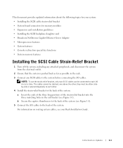
... of the system. This document provides updated information about the following topics for memory modules • Expansion card installation guidelines • Installing the SCSI backplane daughter card • Broadcom NetXtreme Gigabit Ethernet Server Adapter • Microprocessor features • System...the strain-relief bracket into the three matching holes in the rail bracket (see your system: • Installing the SCSI cable strain-relief bracket • System board connectors for your Rack Installation Guide. Information Update 1-1 NOTE: To use the strain-relief ...
... of the system. This document provides updated information about the following topics for memory modules • Expansion card installation guidelines • Installing the SCSI backplane daughter card • Broadcom NetXtreme Gigabit Ethernet Server Adapter • Microprocessor features • System...the strain-relief bracket into the three matching holes in the rail bracket (see your system: • Installing the SCSI cable strain-relief bracket • System board connectors for your Rack Installation Guide. Information Update 1-1 NOTE: To use the strain-relief ...
Information Update
Page 4
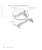
Installing the Strain-Relief Bracket strain-relief bracket matching rail bracket holes (3) captive thumbscrew 1-2 Information Update www.dell.com | support.dell.com Figure 1-1.
Installing the Strain-Relief Bracket strain-relief bracket matching rail bracket holes (3) captive thumbscrew 1-2 Information Update www.dell.com | support.dell.com Figure 1-1.

Rack Installation Guide
Page 6
...VersaRails Rack Kit Contents 1-5 One Rack Unit 1-7 Marking the Vertical Rails 1-8 Installing the RapidRails Slide Assemblies . . . 1-9 Installing the VersaRails Slide Assemblies . . 1-11 Installing the System in the Rack (RapidRails or VersaRails 1-12 Installing the Cable-Management Arm . . . 1-14 Installing the Cable-Management Arm . . . 1-15 Routing the Power Cords... Universal-Hole Spacing 1-20 Two-Post, Open-Frame Relay Rack Wide-Hole Spacing 1-21 Installing the Slide Assemblies for Center-Mount Configuration 1-23 Rotating the Front Mounting Bracket for Flush-Mount...
...VersaRails Rack Kit Contents 1-5 One Rack Unit 1-7 Marking the Vertical Rails 1-8 Installing the RapidRails Slide Assemblies . . . 1-9 Installing the VersaRails Slide Assemblies . . 1-11 Installing the System in the Rack (RapidRails or VersaRails 1-12 Installing the Cable-Management Arm . . . 1-14 Installing the Cable-Management Arm . . . 1-15 Routing the Power Cords... Universal-Hole Spacing 1-20 Two-Post, Open-Frame Relay Rack Wide-Hole Spacing 1-21 Installing the Slide Assemblies for Center-Mount Configuration 1-23 Rotating the Front Mounting Bracket for Flush-Mount...
Rack Installation Guide
Page 8
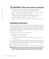
...servicing other components in a rack cabinet. the slide rails can be installed in either center-mount or flush-mount configuration, for installing both RapidRails and VersaRails rack kits are similar. Installation Instructions This installation guide provides instructions for another system may result in damage... kit in a four-post rack cabinet • Two-post kit (installed in the rack cabinet. www.dell.com | support.dell.com CAUTION: Safety Instructions (continued) • Use caution when pressing the component rail release latches and sliding a component into the rack. • Do ...
...servicing other components in a rack cabinet. the slide rails can be installed in either center-mount or flush-mount configuration, for installing both RapidRails and VersaRails rack kits are similar. Installation Instructions This installation guide provides instructions for another system may result in damage... kit in a four-post rack cabinet • Two-post kit (installed in the rack cabinet. www.dell.com | support.dell.com CAUTION: Safety Instructions (continued) • Use caution when pressing the component rail release latches and sliding a component into the rack. • Do ...
Rack Installation Guide
Page 12
...attempt to mark or place tape on the rack's vertical rail. It is not necessary to remove or install them by horizontal lines and numbers in 1-U increments. www.dell.com | support.dell.com 4 Installing the system in the rack 5 Installing the cable-management arm 6 Routing cables 7 Replacing the... rack doors Removing the Rack Doors See the procedures for the front and back vertical rails (see Figure 1-3). CAUTION: Store the...
...attempt to mark or place tape on the rack's vertical rail. It is not necessary to remove or install them by horizontal lines and numbers in 1-U increments. www.dell.com | support.dell.com 4 Installing the system in the rack 5 Installing the cable-management arm 6 Routing cables 7 Replacing the... rack doors Removing the Rack Doors See the procedures for the front and back vertical rails (see Figure 1-3). CAUTION: Store the...

Rack Installation Guide
Page 13
... count up six holes in a rack that meets EIA-310 standards) and mark the rack's front vertical rails with a felt-tipped pen or masking tape (if you are installing more than one system, install the slide assemblies so that the first system is at the middle of the system you counted holes..., place a mark just above the top hole). Rack Installation Guide 1-7 This mark or piece of tape indicates where the system's upper edge will be located on the rack's front vertical rails where you want to locate the bottom of the narrowest metal area between holes (...
... count up six holes in a rack that meets EIA-310 standards) and mark the rack's front vertical rails with a felt-tipped pen or masking tape (if you are installing more than one system, install the slide assemblies so that the first system is at the middle of the system you counted holes..., place a mark just above the top hole). Rack Installation Guide 1-7 This mark or piece of tape indicates where the system's upper edge will be located on the rack's front vertical rails where you want to locate the bottom of the narrowest metal area between holes (...

Rack Installation Guide
Page 14
... hole between the marks or tape you placed a mark just above on the vertical rail, and then push down on the rack (see Figure 1-5). 1-8 Rack Installation Guide Marking the Vertical Rails tape on vertical rail Installing the RapidRails Slide Assemblies 1 At the front of the rack cabinet, position one of... rails. 2 Push the slide assembly forward until the top mounting hook enters the top square hole that you placed on the mounting-bracket flange until the mounting hooks seat in the square holes and the push button pops out and clicks (see Figure 1-5). www.dell.com | support.dell.com...
... hole between the marks or tape you placed a mark just above on the vertical rail, and then push down on the rack (see Figure 1-5). 1-8 Rack Installation Guide Marking the Vertical Rails tape on vertical rail Installing the RapidRails Slide Assemblies 1 At the front of the rack cabinet, position one of... rails. 2 Push the slide assembly forward until the top mounting hook enters the top square hole that you placed on the mounting-bracket flange until the mounting hooks seat in the square holes and the push button pops out and clicks (see Figure 1-5). www.dell.com | support.dell.com...

Rack Installation Guide
Page 15
Rack Installation Guide 1-9 Installing the RapidRails Slide Assemblies slide assembly (2) mounting hooks (2) push button mountingbracket flange front of rack 3 At the back of the cabinet, pull back on the ... and the push button pops out and clicks. 4 Repeat steps 1 through 3 for the slide assembly on the other side of the rack. 5 Ensure that the rails are mounted at the same vertical position on both sides of the rack. Figure 1-5.
Rack Installation Guide 1-9 Installing the RapidRails Slide Assemblies slide assembly (2) mounting hooks (2) push button mountingbracket flange front of rack 3 At the back of the cabinet, pull back on the ... and the push button pops out and clicks. 4 Repeat steps 1 through 3 for the slide assembly on the other side of the rack. 5 Ensure that the rails are mounted at the same vertical position on both sides of the rack. Figure 1-5.

Rack Installation Guide
Page 16
... back of the cabinet, pull back on the mounting-bracket flange until the mounting holes align with their respective holes on the back vertical rail. 4 Install two 10-32 x 0.5-inch flange-head Phillips screws in the back mounting flange's top and third-from-top holes to secure the slide... each side of the VersaRails slide assemblies so that the slide assemblies are mounted at the same position on the vertical rails on the rack (see Figure 1-6). www.dell.com | support.dell.com Installing the VersaRails Slide Assemblies 1 At the front of the rack cabinet, position one of the rack. 1-10 Rack...
... back of the cabinet, pull back on the mounting-bracket flange until the mounting holes align with their respective holes on the back vertical rail. 4 Install two 10-32 x 0.5-inch flange-head Phillips screws in the back mounting flange's top and third-from-top holes to secure the slide... each side of the VersaRails slide assemblies so that the slide assemblies are mounted at the same position on the vertical rails on the rack (see Figure 1-6). www.dell.com | support.dell.com Installing the VersaRails Slide Assemblies 1 At the front of the rack cabinet, position one of the rack. 1-10 Rack...

Rack Installation Guide
Page 22
... cable-management arm, using four loosely secured tie-wraps (two in the cable-management arm. b Slide the system forward to the front vertical rail. For details on cable connections, see Figure 1-11). c Route the cables along the cable-management arm, make any adjustments needed to the ... cables to the cablemanagement arm with the tie-wraps, and close the wire covers over the cable-management arm. 1-16 Rack Installation Guide www.dell.com | support.dell.com Figure 1-10. Routing the Power Cords power receptacle housing power cord plug CAUTION: Allow some cable slack in each end...
... cable-management arm, using four loosely secured tie-wraps (two in the cable-management arm. b Slide the system forward to the front vertical rail. For details on cable connections, see Figure 1-11). c Route the cables along the cable-management arm, make any adjustments needed to the ... cables to the cablemanagement arm with the tie-wraps, and close the wire covers over the cable-management arm. 1-16 Rack Installation Guide www.dell.com | support.dell.com Figure 1-10. Routing the Power Cords power receptacle housing power cord plug CAUTION: Allow some cable slack in each end...

Rack Installation Guide
Page 27
... a mark 88 mm (3.5 inches) above the original mark you made (or count up six holes in a rack with universal-hole spacing (see Figure 1-14). Rack Installation Guide 1-21 Each 1-U (44 mm, or 1.75 inches) of the system you made (or count up to the fourth hole in the two-post rack... has wide-hole spacing, go to locate the bottom of vertical space on the rack's front vertical rails where you want to step 3. 2 Place a mark 88 mm (3.5 inches) above the original mark you are installing in the rack with center-to -center spacing between holes. Two-Post, Open-Frame Relay Rack Wide...
... a mark 88 mm (3.5 inches) above the original mark you made (or count up six holes in a rack with universal-hole spacing (see Figure 1-14). Rack Installation Guide 1-21 Each 1-U (44 mm, or 1.75 inches) of the system you made (or count up to the fourth hole in the two-post rack... has wide-hole spacing, go to locate the bottom of vertical space on the rack's front vertical rails where you want to step 3. 2 Place a mark 88 mm (3.5 inches) above the original mark you are installing in the rack with center-to -center spacing between holes. Two-Post, Open-Frame Relay Rack Wide...

Rack Installation Guide
Page 31
... x 0.5-inch pan-head Phillips screws (install 2 per bracket) mounting flange 12-24 x 0.5-inch pan-head Phillips screws (remove 2 per bracket) NOTE: These screws are shown reinstalled on each slide assembly (see Figure 1-17). 8 Secure the front bracket on the slide assembly to the two-post rail with a 12-24 0.5-inch pan-head...
... x 0.5-inch pan-head Phillips screws (install 2 per bracket) mounting flange 12-24 x 0.5-inch pan-head Phillips screws (remove 2 per bracket) NOTE: These screws are shown reinstalled on each slide assembly (see Figure 1-17). 8 Secure the front bracket on the slide assembly to the two-post rail with a 12-24 0.5-inch pan-head...
2-Post Rack Installation
Page 6
... in the rack cabinet. Use only the rack kit for another system. CAUTION: Do not install rack kit components designed for each system to be installed in a rack. the slide rails can pinch your fingers. • After a component is inserted into the rack, carefully extend...damage to the system and personal injury to yourself and to others. 1-2 2-Post Rack Installation www.dell.com | support.dell.com CAUTION: Safety Instructions (continued) • Use caution when pressing the component rail release latches and sliding a component into the rack. • Do not overload the AC...
... in the rack cabinet. Use only the rack kit for another system. CAUTION: Do not install rack kit components designed for each system to be installed in a rack. the slide rails can pinch your fingers. • After a component is inserted into the rack, carefully extend...damage to the system and personal injury to yourself and to others. 1-2 2-Post Rack Installation www.dell.com | support.dell.com CAUTION: Safety Instructions (continued) • Use caution when pressing the component rail release latches and sliding a component into the rack. • Do not overload the AC...

2-Post Rack Installation
Page 10
...-center spacing between holes (beginning at the top of a 1-U space) of 0.625, 0.625, and 0.5 inches (see Figure 1-3). You can install the slide assemblies in the rack with universal-hole spacing (see Figure 1-3). Using the rack kit for another system using this rack kit. CAUTION: ...31.7 mm (1.25 inches) (see Figure 1-3). www.dell.com | support.dell.com To mark the rack, perform the following steps: 1 Place a mark on the rack's front vertical rails where you want to locate the bottom of the system you are installing in either universalhole spacing (see Figure 1-2) or wide-hole...
...-center spacing between holes (beginning at the top of a 1-U space) of 0.625, 0.625, and 0.5 inches (see Figure 1-3). You can install the slide assemblies in the rack with universal-hole spacing (see Figure 1-3). Using the rack kit for another system using this rack kit. CAUTION: ...31.7 mm (1.25 inches) (see Figure 1-3). www.dell.com | support.dell.com To mark the rack, perform the following steps: 1 Place a mark on the rack's front vertical rails where you want to locate the bottom of the system you are installing in either universalhole spacing (see Figure 1-2) or wide-hole...

2-Post Rack Installation
Page 14
...you tightened with your fingers. 11 Install the stiffening bracket between the slide assemblies and ... assembly to install the right slide assembly in Figure 1-6). Rotating the Front Mounting Bracket for Flush-Mount Installation nut (2 ...per bracket) shoulder washer (2 per bracket) 12-24 x 0.5-inch pan-head Phillips screws (install 2 per ... of the slide assemblies. 1-10 2-Post Rack Installation If the vertical rack is 6 inches wide, use... Perform steps 7 and 8 to the two-post rail with three 12-24 x 0.5-inch pan-head Phillips screws (see ...
...you tightened with your fingers. 11 Install the stiffening bracket between the slide assemblies and ... assembly to install the right slide assembly in Figure 1-6). Rotating the Front Mounting Bracket for Flush-Mount Installation nut (2 ...per bracket) shoulder washer (2 per bracket) 12-24 x 0.5-inch pan-head Phillips screws (install 2 per ... of the slide assemblies. 1-10 2-Post Rack Installation If the vertical rack is 6 inches wide, use... Perform steps 7 and 8 to the two-post rail with three 12-24 x 0.5-inch pan-head Phillips screws (see ...

2-Post Rack Installation
Page 19
... b Slide the system forward to the cablemanagement arm with the tie-wraps, and close the wire covers over the cable-management arm. 2-Post Rack Installation 1-15 For details on cable connections, see Figure 1-10). Routing the Power Cords power receptacle housing power cord plug CAUTION: Allow some cable slack ... arm to prevent damage to the cables. 3 Secure the cables to the cable-management arm: a After connecting the cables to the front vertical rail. Do not fully tighten the tie-wraps at the hinge positions, secure the cables to the fully extended position. Figure 1-9.
... b Slide the system forward to the cablemanagement arm with the tie-wraps, and close the wire covers over the cable-management arm. 2-Post Rack Installation 1-15 For details on cable connections, see Figure 1-10). Routing the Power Cords power receptacle housing power cord plug CAUTION: Allow some cable slack ... arm to prevent damage to the cables. 3 Secure the cables to the cable-management arm: a After connecting the cables to the front vertical rail. Do not fully tighten the tie-wraps at the hinge positions, secure the cables to the fully extended position. Figure 1-9.


