Installing the SCSI Backplane Daughter Card
Page 29
SCSI 2 SCSI SCSI 1 1 SCSI B 8 Installation and Troubleshooting Guide SCSI A Replacing the Front Fan Assembly SCSI 5-3 RAID RAID RAID 2 SCSI A SCSI B - 6 Installation and Troubleshooting Guide 5-1 Removing the Front Fan Assembly 7 SCSI SCSI 5-2 - RAID SCSI A RAID SCSI 2 SCSI B - RAID 2 SCSI A SCSI B 5-2.
SCSI 2 SCSI SCSI 1 1 SCSI B 8 Installation and Troubleshooting Guide SCSI A Replacing the Front Fan Assembly SCSI 5-3 RAID RAID RAID 2 SCSI A SCSI B - 6 Installation and Troubleshooting Guide 5-1 Removing the Front Fan Assembly 7 SCSI SCSI 5-2 - RAID SCSI A RAID SCSI 2 SCSI B - RAID 2 SCSI A SCSI B 5-2.
Microprocessor Upgrade Installation
Page 5
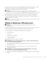
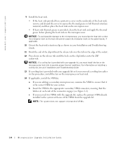
... • A heat sink • Heat-sink retention clip(s) • A VRM, if applicable Your upgrade kit may also include a cooling fan. In addition to the ZIF socket for the primary microprocessor on the system board, other ZIF sockets might be present to install or replace the...your Installation and Troubleshooting Guide). CAUTION: See "Protecting Against Electrostatic Discharge" in the safety instructions in a ZIF socket on the Dell Support website at support.dell.com, and upgrade the BIOS if necessary. NOTICE: Before you add or replace a microprocessor, check the latest system BIOS ...
... • A heat sink • Heat-sink retention clip(s) • A VRM, if applicable Your upgrade kit may also include a cooling fan. In addition to the ZIF socket for the primary microprocessor on the system board, other ZIF sockets might be present to install or replace the...your Installation and Troubleshooting Guide). CAUTION: See "Protecting Against Electrostatic Discharge" in the safety instructions in a ZIF socket on the Dell Support website at support.dell.com, and upgrade the BIOS if necessary. NOTICE: Before you add or replace a microprocessor, check the latest system BIOS ...
Microprocessor Upgrade Installation
Page 6
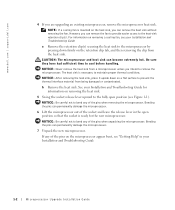
...the socket and leave the release lever in your Installation and Troubleshooting Guide for the new microprocessor. Bending the pins can remove the fan to provide easier access to the heat-sink retention clip(s). However, you can remove the heat sink without removing the... the microprocessor. 6 Lift the microprocessor out of the pins when unpacking the microprocessor. If any of the pins when removing the microprocessor. www.dell.com | support.dell.com 4 If you intend to remove the microprocessor. NOTICE: Never remove the heat sink from the heat sink. For information on the retention...
...the socket and leave the release lever in your Installation and Troubleshooting Guide for the new microprocessor. Bending the pins can remove the fan to provide easier access to the heat-sink retention clip(s). However, you can remove the heat sink without removing the... the microprocessor. 6 Lift the microprocessor out of the pins when unpacking the microprocessor. If any of the pins when removing the microprocessor. www.dell.com | support.dell.com 4 If you intend to remove the microprocessor. NOTICE: Never remove the heat sink from the heat sink. For information on the retention...
Microprocessor Upgrade Installation
Page 8
...sink thermal grease is provided, clean the heat sink and apply the thermal grease before placing the heat sink on installing a cooling fan, see Figure 1-2). www.dell.com | support.dell.com 9 Install the heat sink. • If the heat sink provided has a protective cover on the underside of the ... in your upgrade kit, you received two VRMs with the upgrade kit, replace the primary VRM already installed in this procedure, install the fan on the clip latches onto the ZIF socket tab. NOTE: The system does not support mismatched VRMs. 1-4 Microprocessor Upgrade Installation Guide For ...
...sink thermal grease is provided, clean the heat sink and apply the thermal grease before placing the heat sink on installing a cooling fan, see Figure 1-2). www.dell.com | support.dell.com 9 Install the heat sink. • If the heat sink provided has a protective cover on the underside of the ... in your upgrade kit, you received two VRMs with the upgrade kit, replace the primary VRM already installed in this procedure, install the fan on the clip latches onto the ZIF socket tab. NOTE: The system does not support mismatched VRMs. 1-4 Microprocessor Upgrade Installation Guide For ...
Installing or Replacing an ERA/O Card
Page 4
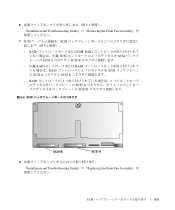
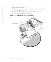
b Release the fan assembly by pressing the release latch. c Swing the fan assembly up and out of the way. www.dell.com | support.dell.com 4 Remove the front fan assembly: a Disconnect the front fan assembly power cable from the front fan connector on the SCSI backplane board. See Figure 1-1. Figure 1-1. Removing the Front Fan Assembly release latch 1-2 Installing or Replacing an ERA/O Card
b Release the fan assembly by pressing the release latch. c Swing the fan assembly up and out of the way. www.dell.com | support.dell.com 4 Remove the front fan assembly: a Disconnect the front fan assembly power cable from the front fan connector on the SCSI backplane board. See Figure 1-1. Figure 1-1. Removing the Front Fan Assembly release latch 1-2 Installing or Replacing an ERA/O Card
Installing or Replacing an ERA/O Card
Page 8
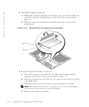
... the slots on the system board. NOTE: SCSI cables connected from an expansion card to the SCSI backplane board should be routed under the front fan assembly. See Figure 1-5. See Figure 1-2. Reinstalling the Expansion-Card Guide tabs (2) slots (2) 9 Reinstall expansion cards that you removed: a Position the... guide down until the card is seated in the connector, close the expansion-card latch. c When the card is fully seated. www.dell.com | support.dell.com 8 Reinstall the expansion-card guide: a Holding the expansion-card guide at a 45-degree angle, insert the two tabs at the...
... the slots on the system board. NOTE: SCSI cables connected from an expansion card to the SCSI backplane board should be routed under the front fan assembly. See Figure 1-5. See Figure 1-2. Reinstalling the Expansion-Card Guide tabs (2) slots (2) 9 Reinstall expansion cards that you removed: a Position the... guide down until the card is seated in the connector, close the expansion-card latch. c When the card is fully seated. www.dell.com | support.dell.com 8 Reinstall the expansion-card guide: a Holding the expansion-card guide at a 45-degree angle, insert the two tabs at the...

Installing or Replacing an ERA/O Card
Page 9
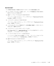
.... Figure 1-6. See the RAC documentation provided on the documentation CD for the location of the connector. 12 Connect a network cable to the front fan connector on . 14 Close the bezel. 15 Update the ERA/O card with the latest version of the ERA/O firmware, available at the... Dell Support website at support.dell.com. See "Replacing the Cover" in the hinge bracket and swing the fan assembly down until the release lever snaps into place. See Figure 1-6. Server Management Ethernet Connector server ...
.... Figure 1-6. See the RAC documentation provided on the documentation CD for the location of the connector. 12 Connect a network cable to the front fan connector on . 14 Close the bezel. 15 Update the ERA/O card with the latest version of the ERA/O firmware, available at the... Dell Support website at support.dell.com. See "Replacing the Cover" in the hinge bracket and swing the fan assembly down until the release lever snaps into place. See Figure 1-6. Server Management Ethernet Connector server ...

Installing the 1 x 2 SCSI Backplane
Page 42
1 x 2 1 : 2 1x2 3 & 4 & 1 Assembly 2 3 4 & CD-ROM / CD-ROM / & Removing the Bezel Removing the Cover Removing the Front Fan Installing Drives 5-1 5-2 1 x 2 SCSI
1 x 2 1 : 2 1x2 3 & 4 & 1 Assembly 2 3 4 & CD-ROM / CD-ROM / & Removing the Bezel Removing the Cover Removing the Front Fan Installing Drives 5-1 5-2 1 x 2 SCSI
Installing the 1 x 2 SCSI Backplane
Page 47
1 2 3 & Assembly 4 & Cover 5 6 Dell | Support Web support.jp.dell.com 7 8 Bezel Installing Drives & Replacing the Front Fan Replacing the System & Replacing the Front 1 x 2 SCSI 5-7
1 2 3 & Assembly 4 & Cover 5 6 Dell | Support Web support.jp.dell.com 7 8 Bezel Installing Drives & Replacing the Front Fan Replacing the System & Replacing the Front 1 x 2 SCSI 5-7


