
Service Manual
Page 5
...3-1 bezel, removal, 4-4 boot routine, observing when troubleshooting, 2-3 bracket, hard-disk drive, removal, 4-10 C cables, DC power, 1-12 CD-ROM drive access indicator location, 1-3 location, 1-4, 4-7 removal, 4-8 computer back/left side internal view, 1-5 ...1-3 technical specifications, 1-19 configuration guidelines, SCSI drives, 1-7 connectors, locations, 1-14, 4-14 control panel assembly location, 1-4 removal, 4-6 D DC power distribution diagram, 1-13 DIMMs ECC, 1-6 installation, 4-15 removal, 4-15 socket population rules, 1-6 diskette drive access indicator location, 1-3 location, 1-4, ...
...3-1 bezel, removal, 4-4 boot routine, observing when troubleshooting, 2-3 bracket, hard-disk drive, removal, 4-10 C cables, DC power, 1-12 CD-ROM drive access indicator location, 1-3 location, 1-4, 4-7 removal, 4-8 computer back/left side internal view, 1-5 ...1-3 technical specifications, 1-19 configuration guidelines, SCSI drives, 1-7 connectors, locations, 1-14, 4-14 control panel assembly location, 1-4 removal, 4-6 D DC power distribution diagram, 1-13 DIMMs ECC, 1-6 installation, 4-15 removal, 4-15 socket population rules, 1-6 diskette drive access indicator location, 1-3 location, 1-4, ...
Service Manual
Page 6
... controller, 1-7 interrupt assignments, list of, 1-17 P PCI expansion cards, 1-6 Plug and Play ISA expansion cards, 1-6 POST beep codes, 3-1 power button, 1-3 power indicator, 1-3 power supply, 1-10 cables, 1-12 connectors, 1-10 DC voltage ranges, 1-10 illustrated, 1-12 power distribution diagram, 1-13 removal, 4-12 precautionary measures, 4-2 R reset button, 1-3 resource conflicts, eliminating, 2-5 2 Dell PowerEdge 2100/180 and 2100/200 Systems Service Manual
... controller, 1-7 interrupt assignments, list of, 1-17 P PCI expansion cards, 1-6 Plug and Play ISA expansion cards, 1-6 POST beep codes, 3-1 power button, 1-3 power indicator, 1-3 power supply, 1-10 cables, 1-12 connectors, 1-10 DC voltage ranges, 1-10 illustrated, 1-12 power distribution diagram, 1-13 removal, 4-12 precautionary measures, 4-2 R reset button, 1-3 resource conflicts, eliminating, 2-5 2 Dell PowerEdge 2100/180 and 2100/200 Systems Service Manual

Service Manual
Page 7
... expansion, 1-6 system battery removal, 4-18 system board component locations, 4-14 illustrated, 1-14 removal, 4-19 system cooling fan, removal, 4-13 system error messages, list of, 3-3 system power supply, 1-10 System Setup program advanced menu, A-6 boot options submenu, A-5 exit menu, A-10 key functions, list of, A-2 main menu, A-3 menus, A-1 screen color combinations, A-3 screen conventions...
... expansion, 1-6 system battery removal, 4-18 system board component locations, 4-14 illustrated, 1-14 removal, 4-19 system cooling fan, removal, 4-13 system error messages, list of, 3-3 system power supply, 1-10 System Setup program advanced menu, A-6 boot options submenu, A-5 exit menu, A-10 key functions, list of, A-2 main menu, A-3 menus, A-1 screen color combinations, A-3 screen conventions...

Service Manual
Page 9
Contents Chapter 1 System Overview 1-1 System Features 1-2 System Memory 1-6 Advanced Expansion Subsystem 1-6 Integrated Server Management 1-6 Video Controller 1-7 Integrated SCSI Controller 1-7 SCSI Hard-Disk Drives 1-7 SCSI Configuration Guidelines 1-7 SCSI ID Numbers 1-8 Device Termination 1-8 System Unit 1-10 System Power Supply 1-10 Pin Assignments for the DC Power Connectors 1-10 DC Power Distribution 1-12 System Board Layout 1-14 System Board Jumpers 1-15 Interrupt Assignments 1-17 DMA Channel Assignments 1-18 Technical Specifications 1-19 v
Contents Chapter 1 System Overview 1-1 System Features 1-2 System Memory 1-6 Advanced Expansion Subsystem 1-6 Integrated Server Management 1-6 Video Controller 1-7 Integrated SCSI Controller 1-7 SCSI Hard-Disk Drives 1-7 SCSI Configuration Guidelines 1-7 SCSI ID Numbers 1-8 Device Termination 1-8 System Unit 1-10 System Power Supply 1-10 Pin Assignments for the DC Power Connectors 1-10 DC Power Distribution 1-12 System Board Layout 1-14 System Board Jumpers 1-15 Interrupt Assignments 1-17 DMA Channel Assignments 1-18 Technical Specifications 1-19 v

Service Manual
Page 10
... Tools 4-1 Precautionary Measures 4-2 Computer Cover 4-3 Front Bezel 4-4 Front-Bezel Inserts 4-5 Control Panel Assembly 4-6 Drives 4-7 Externally Accessible Drives 4-8 Hard-Disk Drives 4-10 Expansion Cards 4-11 System Power Supply 4-12 System Cooling Fan 4-13 System Board Components 4-14 DIMMs 4-15 Microprocessor/Heat Sink Assembly 4-16 System Battery 4-18 System Board Assembly 4-19 System...
... Tools 4-1 Precautionary Measures 4-2 Computer Cover 4-3 Front Bezel 4-4 Front-Bezel Inserts 4-5 Control Panel Assembly 4-6 Drives 4-7 Externally Accessible Drives 4-8 Hard-Disk Drives 4-10 Expansion Cards 4-11 System Power Supply 4-12 System Cooling Fan 4-13 System Board Components 4-14 DIMMs 4-15 Microprocessor/Heat Sink Assembly 4-16 System Battery 4-18 System Board Assembly 4-19 System...

Service Manual
Page 11
...Front Bezel Removal 4-4 Figure 4-3. Control-Panel Assembly Removal 4-6 Figure 4-5. SCSI Termination Jumper Examples 1-9 Figure 1-6. Computer Cover Removal 4-3 Figure 4-2. DC Power Connectors P2, P3, P4, P5, and P6 1-11 Figure 1-8. Front/Right Side Internal View 1-4 Figure 1-4. Front-Bezel Insert Removal 4-5 Figure ... Menu A-8 Exit Menu A-10 Index Figures Figure 1-1. System Board Jumpers 1-15 Figure 4-1. DC Power Connector P1 1-11 Figure 1-7. System Board Components 1-14 Figure 1-12. Back/Left Side Internal View 1-5 Figure 1-5. Computer Orientation 1-3 Figure 1-2....
...Front Bezel Removal 4-4 Figure 4-3. Control-Panel Assembly Removal 4-6 Figure 4-5. SCSI Termination Jumper Examples 1-9 Figure 1-6. Computer Cover Removal 4-3 Figure 4-2. DC Power Connectors P2, P3, P4, P5, and P6 1-11 Figure 1-8. Front/Right Side Internal View 1-4 Figure 1-4. Front-Bezel Insert Removal 4-5 Figure ... Menu A-8 Exit Menu A-10 Index Figures Figure 1-1. System Board Jumpers 1-15 Figure 4-1. DC Power Connector P1 1-11 Figure 1-7. System Board Components 1-14 Figure 1-12. Back/Left Side Internal View 1-5 Figure 1-5. Computer Orientation 1-3 Figure 1-2....

Service Manual
Page 12
... A-5 Advanced Menu Categories A-7 Security Menu Categories A-9 Exit Menu Categories A-11 viii System Cooling-Fan Removal 4-13 Figure 4-12. Security Menu A-8 Figure A-5. Table A-1. Main Menu A-3 Figure A-2. Power Supply Removal 4-12 Figure 4-11. Figure 4-7. Table A-4.
... A-5 Advanced Menu Categories A-7 Security Menu Categories A-9 Exit Menu Categories A-11 viii System Cooling-Fan Removal 4-13 Figure 4-12. Security Menu A-8 Figure A-5. Table A-1. Main Menu A-3 Figure A-2. Power Supply Removal 4-12 Figure 4-11. Figure 4-7. Table A-4.

Service Manual
Page 15
..., upgradable, server systems, which increases the internal operating frequency to a multiple of the system board to a faster, more powerful microprocessor when one becomes available. Chapter 1 System Overview The Dell® PowerEdge® 2100/180 and 2100/200 systems, covered in a zero insertion force (ZIF) socket on the system board. This allows upgrading of the system...
..., upgradable, server systems, which increases the internal operating frequency to a multiple of the system board to a faster, more powerful microprocessor when one becomes available. Chapter 1 System Overview The Dell® PowerEdge® 2100/180 and 2100/200 systems, covered in a zero insertion force (ZIF) socket on the system board. This allows upgrading of the system...
Service Manual
Page 16
...system voltages and temperatures • 3.5-inch diskette drive and a CD-ROM drive standard in this chapter. 1-2 Dell PowerEdge 2100/180 and 2100/200 Systems Service Manual troller on the system board • Advanced combination EISA and PCI expansion subsystem •... Three EISA and three PCI expansion-card slots (none of the expansion-card slots are briefly described in externally accessi- For a complete list of the sys- ble drive bays • Recessed power...
...system voltages and temperatures • 3.5-inch diskette drive and a CD-ROM drive standard in this chapter. 1-2 Dell PowerEdge 2100/180 and 2100/200 Systems Service Manual troller on the system board • Advanced combination EISA and PCI expansion subsystem •... Three EISA and three PCI expansion-card slots (none of the expansion-card slots are briefly described in externally accessi- For a complete list of the sys- ble drive bays • Recessed power...

Service Manual
Page 17
... computer Figure 1-1. System Overview 1-3 Computer Orientation 3.5-inch diskette drive diskette-drive access indicator CD-ROM drive CD-ROM-drive access indicator (BUSY) third drive bay power button power indicator hard-disk-drive access indicator reset button Figure 1-2. When following the text in Figure 1-1.
... computer Figure 1-1. System Overview 1-3 Computer Orientation 3.5-inch diskette drive diskette-drive access indicator CD-ROM drive CD-ROM-drive access indicator (BUSY) third drive bay power button power indicator hard-disk-drive access indicator reset button Figure 1-2. When following the text in Figure 1-1.
Service Manual
Page 18
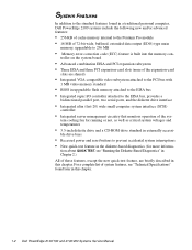
Front/Right Side Internal View system board mounting plate 1-4 Dell PowerEdge 2100/180 and 2100/200 Systems Service Manual system power supply control panel assembly diskette drive CD-ROM drive third drive bay diskette controller cable power cables control panel cable SCSI cable system cooling fan internal hard-disk drive cage Figure 1-3.
Front/Right Side Internal View system board mounting plate 1-4 Dell PowerEdge 2100/180 and 2100/200 Systems Service Manual system power supply control panel assembly diskette drive CD-ROM drive third drive bay diskette controller cable power cables control panel cable SCSI cable system cooling fan internal hard-disk drive cage Figure 1-3.

Service Manual
Page 19
voltage selection switch AC power input connector I/O panel connectors externally-accessible drive bays (3) SCSI hard-disk drive cage SCSI cable hard-disk-drive power cables Figure 1-4. Back/Left Side Internal View system board System Overview 1-5
voltage selection switch AC power input connector I/O panel connectors externally-accessible drive bays (3) SCSI hard-disk drive cage SCSI cable hard-disk-drive power cables Figure 1-4. Back/Left Side Internal View system board System Overview 1-5

Service Manual
Page 24
... -13.20 VDC 0.3 A -5 VDC -4.50 to -5.50 VDC 0.3 A +5 VFP3 +4.75 to their corresponding power input connectors on +5 VDC and +3.3 VDC shall not exceed 170 W. 2 The total power of the connectors. 1-10 Dell PowerEdge 2100/180 and 2100/200 Systems Service Manual The system power supply provides the DC operating voltages and currents listed in Table 1-1. Figures 1-6, 1-7, and...
... -13.20 VDC 0.3 A -5 VDC -4.50 to -5.50 VDC 0.3 A +5 VFP3 +4.75 to their corresponding power input connectors on +5 VDC and +3.3 VDC shall not exceed 170 W. 2 The total power of the connectors. 1-10 Dell PowerEdge 2100/180 and 2100/200 Systems Service Manual The system power supply provides the DC operating voltages and currents listed in Table 1-1. Figures 1-6, 1-7, and...

Service Manual
Page 25
...) +5 VFP (purple) 1 Pin 11 - PSON# should measure between +4 and +5 VDC except when the power button on and operating to its active-low state. 2 Pin 5 - DC Power Connectors P2, P3, P4, P5, and P6 System Overview 1-11 Figure 1-6. DC Power Connector P1 1234 P2, P3, P5, P6 +5 VDC (red) common (black) common (black) +12... VDC (yellow) P4 12 34 +12 VDC (yellow) common (black) common (black) +5 VDC (red) Figure 1-7. PWRGOOD should measure between +4 and +5 VDC when the power supply is on the front panel is pressed, taking PSON# to indicate that all...
...) +5 VFP (purple) 1 Pin 11 - PSON# should measure between +4 and +5 VDC except when the power button on and operating to its active-low state. 2 Pin 5 - DC Power Connectors P2, P3, P4, P5, and P6 System Overview 1-11 Figure 1-6. DC Power Connector P1 1234 P2, P3, P5, P6 +5 VDC (red) common (black) common (black) +12... VDC (yellow) P4 12 34 +12 VDC (yellow) common (black) common (black) +5 VDC (red) Figure 1-7. PWRGOOD should measure between +4 and +5 VDC when the power supply is on the front panel is pressed, taking PSON# to indicate that all...

Service Manual
Page 26
DC Power Cables 1-12 Dell PowerEdge 2100/180 and 2100/200 Systems Service Manual P7 1 2 34 5 6 +3.3 VDC (blue/white) +3.3 VDC (blue/white) +3.3 VDC (blue/white) common (black) common (black) common (black) Figure 1-8. DC Power Connectors P7 DC Power Distribution Figures 1-9 and 1-10 provide the following information about DC power distribution: • Power-supply connector identification • Power cable connections for diskette, tape, CD-ROM, and hard-disk drives • Power distribution to sockets and connectors on the system board P1 P4 P5 P7 P6 P3 P2 Figure 1-9.
DC Power Cables 1-12 Dell PowerEdge 2100/180 and 2100/200 Systems Service Manual P7 1 2 34 5 6 +3.3 VDC (blue/white) +3.3 VDC (blue/white) +3.3 VDC (blue/white) common (black) common (black) common (black) Figure 1-8. DC Power Connectors P7 DC Power Distribution Figures 1-9 and 1-10 provide the following information about DC power distribution: • Power-supply connector identification • Power cable connections for diskette, tape, CD-ROM, and hard-disk drives • Power distribution to sockets and connectors on the system board P1 P4 P5 P7 P6 P3 P2 Figure 1-9.

Service Manual
Page 27
... FAN PANEL SPKR KYBD MOUSE System Overview 1-13 keyboard controller system board +3 VDC system power supply P1 PSON# +5 VFP +5 VDC -5 VDC +12 VDC -12 VDC POWER power management logic PWRGOOD PSON# +5 VFP +5 VDC -5 VDC +12 VDC -12 VDC RTC/ NVRAM P7 +3.3 VDC POWER3V battery +3.3 VDC +5 VDC +12 VDC -12 VDC PCI4 through ...
... FAN PANEL SPKR KYBD MOUSE System Overview 1-13 keyboard controller system board +3 VDC system power supply P1 PSON# +5 VFP +5 VDC -5 VDC +12 VDC -12 VDC POWER power management logic PWRGOOD PSON# +5 VFP +5 VDC -5 VDC +12 VDC -12 VDC RTC/ NVRAM P7 +3.3 VDC POWER3V battery +3.3 VDC +5 VDC +12 VDC -12 VDC PCI4 through ...

Service Manual
Page 28
... Components 1-14 Dell PowerEdge 2100/180 and 2100/200 Systems Service Manual System Board Layout The subsections that follow provide service-related information about the system board components. fan connector (FAN) integrated SCSI port connector (SCSI) top of the computer 3-volt power connector (POWER3V) keyboard (bottom) and mouse (top) connectors (KYBD/MOUSE) power connector (POWER) control-panel...
... Components 1-14 Dell PowerEdge 2100/180 and 2100/200 Systems Service Manual System Board Layout The subsections that follow provide service-related information about the system board components. fan connector (FAN) integrated SCSI port connector (SCSI) top of the computer 3-volt power connector (POWER3V) keyboard (bottom) and mouse (top) connectors (KYBD/MOUSE) power connector (POWER) control-panel...

Service Manual
Page 34
... . . . . . 34-pin connector Controls and Indicators Reset control push button Power control push button Power indicator green LED Diskette-drive access indicator green LED Hard-disk drive access indicator green LED CD-ROM drive access indicator green LED 1-20 Dell PowerEdge 2100/180 and 2100/200 Systems Service Manual Technical Specifications (Continued) Integrated SCSI Controller Type...
... . . . . . 34-pin connector Controls and Indicators Reset control push button Power control push button Power indicator green LED Diskette-drive access indicator green LED Hard-disk drive access indicator green LED CD-ROM drive access indicator green LED 1-20 Dell PowerEdge 2100/180 and 2100/200 Systems Service Manual Technical Specifications (Continued) Integrated SCSI Controller Type...

Service Manual
Page 35
... Overview 1-21 Technical Specifications (Continued) Video Video type ATI mach64 (264VT) PCI video controller with integrated VGA connector Video memory (standard 1 MB (not upgradable) Power DC power supply: Wattage 230 W Voltage 90 to 135 V at 60 Hz; 180 to 265 V at 50 Hz Backup battery 3.0-V CR2032 lithium coin cell Physical Height 44...
... Overview 1-21 Technical Specifications (Continued) Video Video type ATI mach64 (264VT) PCI video controller with integrated VGA connector Video memory (standard 1 MB (not upgradable) Power DC power supply: Wattage 230 W Voltage 90 to 135 V at 60 Hz; 180 to 265 V at 50 Hz Backup battery 3.0-V CR2032 lithium coin cell Physical Height 44...
Service Manual
Page 38
...obvious damage or improper settings. For a serial mouse, the mouse interface cable must be necessary to replace the keyboard. 2-2 Dell PowerEdge 2100/180 and 2100/200 Systems Service Manual Inspect all peripherals. 2. For proper settings of the video monitor controls, see the documentation for the monitor... more keys are properly connected to the system unit, the monitor and peripherals, and their labels. If present, verify that all power cables are sticking, it may be secure enough to ensure a firm connection. 4. To perform the external visual inspection, follow these...
...obvious damage or improper settings. For a serial mouse, the mouse interface cable must be necessary to replace the keyboard. 2-2 Dell PowerEdge 2100/180 and 2100/200 Systems Service Manual Inspect all peripherals. 2. For proper settings of the video monitor controls, see the documentation for the monitor... more keys are properly connected to the system unit, the monitor and peripherals, and their labels. If present, verify that all power cables are sticking, it may be secure enough to ensure a firm connection. 4. To perform the external visual inspection, follow these...


