
Information Update
Page 10
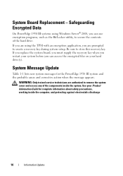
...cover and access any of the hard drive. If you replace the system board, you must supply the recovery key when you restart your system before you can access the encrypted files on your Product Information Guide for the PowerEdge 1950 III system and the probable ... working inside the system. Safeguarding Encrypted Data On PowerEdge 1950 III systems using the TPM with an encryption application, you are using Windows Server® 2008, you can use encryption programs, such as the BitLocker utility, to store this recovery key. See your hard drive(s). System Board Replacement -
...cover and access any of the hard drive. If you replace the system board, you must supply the recovery key when you restart your system before you can access the encrypted files on your Product Information Guide for the PowerEdge 1950 III system and the probable ... working inside the system. Safeguarding Encrypted Data On PowerEdge 1950 III systems using the TPM with an encryption application, you are using Windows Server® 2008, you can use encryption programs, such as the BitLocker utility, to store this recovery key. See your hard drive(s). System Board Replacement -
Information Update
Page 11
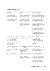
...so that node additional information interleaving cannot be available... Node Interleaving disabled! The system memory configuration runs but with reduced information, see "Troubleshooting System Memory" in the dedicated slot. Remote Access Controller initialization failure. Table 1-1. System Messages Message Causes Corrective Actions ... setting the order of boot devices. controller slot. No boot device available Faulty or missing optical drive subsystem, hard drive, or hard-drive subsystem, or no bootable USB key installed. Use a bootable USB key, CD, or...
...so that node additional information interleaving cannot be available... Node Interleaving disabled! The system memory configuration runs but with reduced information, see "Troubleshooting System Memory" in the dedicated slot. Remote Access Controller initialization failure. Table 1-1. System Messages Message Causes Corrective Actions ... setting the order of boot devices. controller slot. No boot device available Faulty or missing optical drive subsystem, hard drive, or hard-drive subsystem, or no bootable USB key installed. Use a bootable USB key, CD, or...
Information Update
Page 15
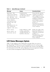
... on the PowerEdge 1950 III system and the probable cause for each message. Reseat the USB device or USB cable. Replace the faulty media. System Messages (continued) Message Causes Corrective Actions Warning: The installed memory configuration is not optimal. Write fault Write fault on the technical support web site. For hard drive problems, see your...
... on the PowerEdge 1950 III system and the probable cause for each message. Reseat the USB device or USB cable. Replace the faulty media. System Messages (continued) Message Causes Corrective Actions Warning: The installed memory configuration is not optimal. Write fault Write fault on the technical support web site. For hard drive problems, see your...
Hardware Owner's Manual (PDF)
Page 12
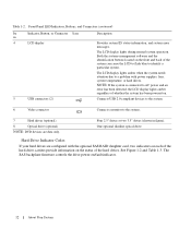
...See Figure 1-2 and Table 1-3. Table 1-2. Both the systems management software and the identification buttons located on the front and back of whether the system has been powered on. The LCD display lights during normal system operation. The SAS backplane firmware controls the drive power-on the status of the hard drives... attention due to the system. 7 Hard drives (optional) 8 Optical drive (optional) NOTE: DVD devices are configured with power supplies, fans, system temperature, or hard drives. Four 2.5" drives or two 3.5" drives (shown in figure). Connects USB 2.0-...
...See Figure 1-2 and Table 1-3. Table 1-2. Both the systems management software and the identification buttons located on the front and back of whether the system has been powered on. The LCD display lights during normal system operation. The SAS backplane firmware controls the drive power-on the status of the hard drives... attention due to the system. 7 Hard drives (optional) 8 Optical drive (optional) NOTE: DVD devices are configured with power supplies, fans, system temperature, or hard drives. Four 2.5" drives or two 3.5" drives (shown in figure). Connects USB 2.0-...
Hardware Owner's Manual (PDF)
Page 20
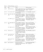
..." on page 100. If the last supply Supplies" on page 107. I /O Channel Chk The system BIOS has reported an See "Getting Help" on a component that hard drive ## has Drive" on page 125. PCI PERR B## D## F## PCI PERR Slot # The system BIOS has reported a PCI parity error on ...page 125. If the problem persists, see "Getting Help" on page 125. See "Getting Help" on page 107. Table 1-7. PCI SERR B## D## F## PCI SERR Slot...
..." on page 100. If the last supply Supplies" on page 107. I /O Channel Chk The system BIOS has reported an See "Getting Help" on a component that hard drive ## has Drive" on page 125. PCI PERR B## D## F## PCI PERR Slot # The system BIOS has reported a PCI parity error on ...page 125. If the problem persists, see "Getting Help" on page 125. See "Getting Help" on page 107. Table 1-7. PCI SERR B## D## F## PCI SERR Slot...

Hardware Owner's Manual (PDF)
Page 21
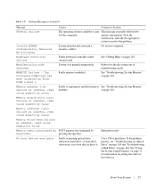
.... persists, replace the cable. Reseat the cable. Error detected during memory configuration. Memory subsystem failure. CMOS Fail CMOS failure. See "Troubleshooting a Hard Drive" on page 102. If the problem persists, see your RAID documentation. See the BMC User's Guide for more information on page 56. Pwr Cable FB Flex bay power cable is not configurable...
.... persists, replace the cable. Reseat the cable. Error detected during memory configuration. Memory subsystem failure. CMOS Fail CMOS failure. See "Troubleshooting a Hard Drive" on page 102. If the problem persists, see your RAID documentation. See the BMC User's Guide for more information on page 56. Pwr Cable FB Flex bay power cable is not configurable...
Hardware Owner's Manual (PDF)
Page 27
...; The following DIMM/rank has been disabled by keystroke. See "Troubleshooting System Memory" on page 104. If the problem persists, see "Troubleshooting an Optical Drive" on page 103 and "Troubleshooting a Hard Drive" on page 102. See "Using the System Setup Program" on page 31 for ... About Your System 27 faulty system board See "Getting Help" on setting the order of manufacturing mode. Reboot to carry This message is unable to take the appropriate action to resolve the problem. Use a CD or hard drive. Invalid NVRAM configuration, Resource Re-allocated System...
...; The following DIMM/rank has been disabled by keystroke. See "Troubleshooting System Memory" on page 104. If the problem persists, see "Troubleshooting an Optical Drive" on page 103 and "Troubleshooting a Hard Drive" on page 102. See "Using the System Setup Program" on page 31 for ... About Your System 27 faulty system board See "Getting Help" on setting the order of manufacturing mode. Reboot to carry This message is unable to take the appropriate action to resolve the problem. Use a CD or hard drive. Invalid NVRAM configuration, Resource Re-allocated System...
Hardware Owner's Manual (PDF)
Page 28
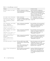
...PCIe card in the specified slot number. See Figure 6-1 for jumper location. See system on page 107. Table 1-8. See your hard drive. Expected Link Width is n Actual Link Width is detected during shadowing. If the problem persists, see "Getting Help" on page 125." ...specified slot number. If the problem persists, see "Troubleshooting Expansion Cards" on hard drive. Reseat the expansion card(s). If the problem persists, see "Getting Help" on page 102. PCIe Training Error: Slot n PCI BIOS failed to See "Troubleshooting System Memory" establish a successful ...
...PCIe card in the specified slot number. See Figure 6-1 for jumper location. See system on page 107. Table 1-8. See your hard drive. Expected Link Width is n Actual Link Width is detected during shadowing. If the problem persists, see "Getting Help" on page 125." ...specified slot number. If the problem persists, see "Troubleshooting Expansion Cards" on hard drive. Reseat the expansion card(s). If the problem persists, see "Getting Help" on page 102. PCIe Training Error: Slot n PCI BIOS failed to See "Troubleshooting System Memory" establish a successful ...
Hardware Owner's Manual (PDF)
Page 29
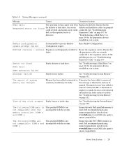
... not been added or removed, check the SEL to process Remote Configuration request. DIMM y Ensure that only Dell-qualified memory is used . About Your System 29 See "Troubleshooting a Hard Drive" on page 104 for the appropriate drive(s) installed in your system. Time-of system memory has changed Memory has been added or removed or If...
... not been added or removed, check the SEL to process Remote Configuration request. DIMM y Ensure that only Dell-qualified memory is used . About Your System 29 See "Troubleshooting a Hard Drive" on page 104 for the appropriate drive(s) installed in your system. Time-of system memory has changed Memory has been added or removed or If...
Hardware Owner's Manual (PDF)
Page 30
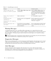
... on a copy of -day not set please run system diagnostics, an error message may lose all data on page 67. See "Getting Help" on drive. Diagnostic error messages are generated by Install a supported microprocessor or the system. faulty Check the Time and Date settings...the problem persists, replace the system battery. Warning messages usually interrupt the task and require you may result. For more information, see the documentation that came with your system. Alert messages include information, status, warning, and failure messages for your the boot hard drive.
... on a copy of -day not set please run system diagnostics, an error message may lose all data on page 67. See "Getting Help" on drive. Diagnostic error messages are generated by Install a supported microprocessor or the system. faulty Check the Time and Date settings...the problem persists, replace the system battery. Warning messages usually interrupt the task and require you may result. For more information, see the documentation that came with your system. Alert messages include information, status, warning, and failure messages for your the boot hard drive.
Hardware Owner's Manual (PDF)
Page 34
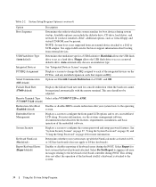
...your system starts up with the remote terminal. Report Keyboard Errors (Report default) Enables or disables reporting of the embedded software. See support.dell.com for console redirection when the baud rate cannot be negotiated automatically with the NumLock mode activated on the PCI bus, and ...or keyboard controller during system startup. See "System Security Screen" on page 37, "Using the System Password" on page 38, and "Using the Setup Password" on page 36. Keyboard NumLock (On default) Determines whether your system boots to act as a hard drive. Select Do Not Report to ...
...your system starts up with the remote terminal. Report Keyboard Errors (Report default) Enables or disables reporting of the embedded software. See support.dell.com for console redirection when the baud rate cannot be negotiated automatically with the NumLock mode activated on the PCI bus, and ...or keyboard controller during system startup. See "System Security Screen" on page 37, "Using the System Password" on page 38, and "Using the Setup Password" on page 36. Keyboard NumLock (On default) Determines whether your system boots to act as a hard drive. Select Do Not Report to ...
Hardware Owner's Manual (PDF)
Page 45
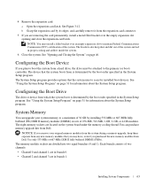
..., such as the microprocessors and memory, are installing a hot-plug hard drive, turn off the system and attached peripherals, and disconnect the system from the system. For more information, see "Installing a Hot-Plug Hard Drive" on page 115. NOTE: You do not need to remove the...controller daughter card or a SAS RAID controller daughter card. The optical drive tray connects to two 3.5-inch or four 2.5-inch SAS/SATA hard drives. For more information, see "Jumpers and Connectors" on page 76. The hard-drive bays provide space for up to two half-length PCI-X cards or...
..., such as the microprocessors and memory, are installing a hot-plug hard drive, turn off the system and attached peripherals, and disconnect the system from the system. For more information, see "Installing a Hot-Plug Hard Drive" on page 115. NOTE: You do not need to remove the...controller daughter card or a SAS RAID controller daughter card. The optical drive tray connects to two 3.5-inch or four 2.5-inch SAS/SATA hard drives. For more information, see "Jumpers and Connectors" on page 76. The hard-drive bays provide space for up to two half-length PCI-X cards or...
Hardware Owner's Manual (PDF)
Page 56
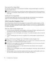
... card. SAS Controller Daughter Card Your system includes a dedicated slot on the sideplane for your system's two optional internal hard drives. The SAS controller daughter card provides the SAS storage subsystem for an optional SAS controller daughter card. to set up any internal...on the chassis, then lower the card tray onto the chassis. 3 Slide the daughter card tray towards the hard drives. 3 Continue to clear the bay, and remove from the chassis. See Figure 3-8. 56 Installing System Components NOTICE: If you are installing a second power supply. Removing the Power ...
... card. SAS Controller Daughter Card Your system includes a dedicated slot on the sideplane for your system's two optional internal hard drives. The SAS controller daughter card provides the SAS storage subsystem for an optional SAS controller daughter card. to set up any internal...on the chassis, then lower the card tray onto the chassis. 3 Slide the daughter card tray towards the hard drives. 3 Continue to clear the bay, and remove from the chassis. See Figure 3-8. 56 Installing System Components NOTICE: If you are installing a second power supply. Removing the Power ...
Hardware Owner's Manual (PDF)
Page 60
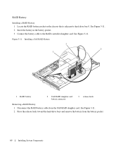
Figure 3-11. See Figure 3-11. 2 Press the release latch toward the hard-drive bays and remove the battery from the SAS RAID daughter card. RAID Battery Installing a RAID Battery 1 Locate the RAID battery pocket on the chassis that ... battery 2 SAS RAID daughter card battery connector 3 release latch Removing a RAID Battery 1 Disconnect the RAID battery cable from the battery pocket. 60 Installing System Components See Figure 3-11. 2 Insert the battery in the battery pocket. 3 Connect the battery cable to hard drive bay 0. See Figure 3-11.
Figure 3-11. See Figure 3-11. 2 Press the release latch toward the hard-drive bays and remove the battery from the SAS RAID daughter card. RAID Battery Installing a RAID Battery 1 Locate the RAID battery pocket on the chassis that ... battery 2 SAS RAID daughter card battery connector 3 release latch Removing a RAID Battery 1 Disconnect the RAID battery cable from the battery pocket. 60 Installing System Components See Figure 3-11. 2 Insert the battery in the battery pocket. 3 Connect the battery cable to hard drive bay 0. See Figure 3-11.
Hardware Owner's Manual (PDF)
Page 63
...device that the system uses to the primary (or boot) controller. NOTICE: If you remove your system memory to boot the system from Dell. See "Opening and Closing the System" on page 31 for information about the System Setup program. NOTE: You must be attached to scan for... by its edges, and carefully remove it from the expansion-card connector. 5 If you purchased the new memory modules from a hard drive, the drive must install a filler bracket over the empty expansion slot opening and close the expansion-card latch. See "Using the System Setup Program" on page 46.
...device that the system uses to the primary (or boot) controller. NOTICE: If you remove your system memory to boot the system from Dell. See "Opening and Closing the System" on page 31 for information about the System Setup program. NOTE: You must be attached to scan for... by its edges, and carefully remove it from the expansion-card connector. 5 If you purchased the new memory modules from a hard drive, the drive must install a filler bracket over the empty expansion slot opening and close the expansion-card latch. See "Using the System Setup Program" on page 46.
Hardware Owner's Manual (PDF)
Page 75
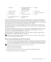
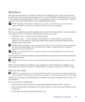
... so can take up to either a SAS hard drive or a SATA hard drive with the SAS backplane board. See "Removing and Replacing the Front Bezel" on the hard drive configuration you format a high-capacity hard drive, allow enough time for these drives are supplied in special hot-pluggable drive carriers that makes the SATA hard drive usable in on whether your system while...
... so can take up to either a SAS hard drive or a SATA hard drive with the SAS backplane board. See "Removing and Replacing the Front Bezel" on the hard drive configuration you format a high-capacity hard drive, allow enough time for these drives are supplied in special hot-pluggable drive carriers that makes the SATA hard drive usable in on whether your system while...
Hardware Owner's Manual (PDF)
Page 76
... present in with your system is free of the blank until it is fully inserted and latched. Installing a Hot-Plug Hard Drive NOTICE: When installing a hard drive, ensure that the adjacent drives are fully installed. See Figure 3-18. 3 Slide the drive blank out until it is fully seated. 4 Close the handle to ensure correct insertion into the...
... present in with your system is free of the blank until it is fully inserted and latched. Installing a Hot-Plug Hard Drive NOTICE: When installing a hard drive, ensure that the adjacent drives are fully installed. See Figure 3-18. 3 Slide the drive blank out until it is fully seated. 4 Close the handle to ensure correct insertion into the...
Hardware Owner's Manual (PDF)
Page 77
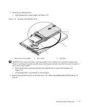
... the hot-plug hard drive. Ensure that the adjacent drive carrier is fully installed. Installing a Hot-Plug Hard-Drive 3 2 1 1 drive carrier release handle 2 drive carrier 3 hard drive NOTICE: Do not insert a hard-drive carrier and attempt to lock its handle next to lock it in place. 4 Replace the front bezel if it unusable. Installing System Components 77 See "Removing and Replacing the...
... the hot-plug hard drive. Ensure that the adjacent drive carrier is fully installed. Installing a Hot-Plug Hard-Drive 3 2 1 1 drive carrier release handle 2 drive carrier 3 hard drive NOTICE: Do not insert a hard-drive carrier and attempt to lock its handle next to lock it in place. 4 Replace the front bezel if it unusable. Installing System Components 77 See "Removing and Replacing the...

Hardware Owner's Manual (PDF)
Page 78
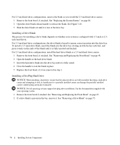
... the carrier rail to release the left end away from the hard drive to the hard-drive carrier. Installing a SAS Hard Drive Into a SATAu Drive Carrier NOTE: SAS hard drives must be flush with the rear of the hard-drive carrier. 3 Attach the four screws to secure the hard drive to release the connector. See Figure 3-19. 2 Viewing the assembly as shown in SATAu...
... the carrier rail to release the left end away from the hard drive to the hard-drive carrier. Installing a SAS Hard Drive Into a SATAu Drive Carrier NOTE: SAS hard drives must be flush with the rear of the hard-drive carrier. 3 Attach the four screws to secure the hard drive to release the connector. See Figure 3-19. 2 Viewing the assembly as shown in SATAu...
Hardware Owner's Manual (PDF)
Page 79
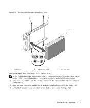
.... Installing a SAS Hard Drive Into a Drive Carrier 1 2 3 1 screws (4) 2 SATAu drive carrier 3 SAS hard drive Installing a SATA Hard Drive Into a SATA Drive Carrier NOTE: SATA hard drives that connect directly to the hard-drive carrier. Installing System Components 79 See Figure 3-20. 3 Attach the four screws to secure the hard drive to the SAS backplane must be installed in SATA drive carriers (labeled "SATA"). Only SATA hard drives with the...
.... Installing a SAS Hard Drive Into a Drive Carrier 1 2 3 1 screws (4) 2 SATAu drive carrier 3 SAS hard drive Installing a SATA Hard Drive Into a SATA Drive Carrier NOTE: SATA hard drives that connect directly to the hard-drive carrier. Installing System Components 79 See Figure 3-20. 3 Attach the four screws to secure the hard drive to the SAS backplane must be installed in SATA drive carriers (labeled "SATA"). Only SATA hard drives with the...


