
Installing a SATA Optical Drive
Page 1
Dell™ PowerEdge™ 19x0 and 29x0 Systems Installing a SATA Optical Drive
Dell™ PowerEdge™ 19x0 and 29x0 Systems Installing a SATA Optical Drive

Installing a SATA Optical Drive
Page 3
... 1900 systems only: Perform the following steps. See "Opening the System" in your Hardware Owner's Manual. 4 PowerEdge 1950 systems only: Disconnect and remove the SAS controller daughter card. Installing a SATA Optical Drive These instructions apply to Dell™ PowerEdge™ systems to remove the system cover and access any of the components inside the system...
... 1900 systems only: Perform the following steps. See "Opening the System" in your Hardware Owner's Manual. 4 PowerEdge 1950 systems only: Disconnect and remove the SAS controller daughter card. Installing a SATA Optical Drive These instructions apply to Dell™ PowerEdge™ systems to remove the system cover and access any of the components inside the system...
Installing a SATA Optical Drive
Page 4
On PowerEdge 1950 systems, the existing optical drive tray must remove the old drive and interposer card from the drive carrier and install the new SATA drive in the side of the tray. PowerEdge 2970, 2950, and 1950 For PowerEdge 2970 and 2950 systems, the optical drive tray that shipped with the SATA ...holes in the same carrier. If you must be replaced with the drive tray provided with the system is used for the SATA optical drive. Replacing a PowerEdge 2950 or 2970 Optical Drive NOTE: If you are replacing an existing IDE optical drive, you are replacing an existing optical...
On PowerEdge 1950 systems, the existing optical drive tray must remove the old drive and interposer card from the drive carrier and install the new SATA drive in the side of the tray. PowerEdge 2970, 2950, and 1950 For PowerEdge 2970 and 2950 systems, the optical drive tray that shipped with the SATA ...holes in the same carrier. If you must be replaced with the drive tray provided with the system is used for the SATA optical drive. Replacing a PowerEdge 2950 or 2970 Optical Drive NOTE: If you are replacing an existing IDE optical drive, you are replacing an existing optical...

Installing a SATA Optical Drive
Page 5
... Drive NOTE: The replacement drive tray provided in the side of the SATA optical drive into the tray until the pins on the carrier align with the holes in the installation kit must be used with PowerEdge 1950 systems. If you are replacing an existing optical drive, do not reuse ...the interposer board attached to the tray. See Figure 1-2. Installing a SATA Optical Drive 5 Spread the side rails of the replacement drive tray and ...
... Drive NOTE: The replacement drive tray provided in the side of the SATA optical drive into the tray until the pins on the carrier align with the holes in the installation kit must be used with PowerEdge 1950 systems. If you are replacing an existing optical drive, do not reuse ...the interposer board attached to the tray. See Figure 1-2. Installing a SATA Optical Drive 5 Spread the side rails of the replacement drive tray and ...

Installing a SATA Optical Drive
Page 6
... in the fan bracket and follow the power cable routing to the SATA_A connector on the system board. 6 Installing a SATA Optical Drive See Figure 1-3. c Connect the cable to the power supply bays. PowerEdge 1950 1 Insert the optical drive tray into the system until it is fully inserted and locked into the cable path...
... in the fan bracket and follow the power cable routing to the SATA_A connector on the system board. 6 Installing a SATA Optical Drive See Figure 1-3. c Connect the cable to the power supply bays. PowerEdge 1950 1 Insert the optical drive tray into the system until it is fully inserted and locked into the cable path...

Installing a SATA Optical Drive
Page 7
... "Closing the System" in your Hardware Owner's Manual. 6 Close the system. Installing the SATA Optical Drive - See "SAS Controller Daughter Card" in the PowerEdge 1950 2 1 3 4 6 5 1 SATA data cable 3 chipset shroud 5 SATA power cable 2 SATA_A connector on the system and attached peripherals. PowerEdge 2970 or 2950 1 Insert the optical drive tray into the system until it is...
... "Closing the System" in your Hardware Owner's Manual. 6 Close the system. Installing the SATA Optical Drive - See "SAS Controller Daughter Card" in the PowerEdge 1950 2 1 3 4 6 5 1 SATA data cable 3 chipset shroud 5 SATA power cable 2 SATA_A connector on the system and attached peripherals. PowerEdge 2970 or 2950 1 Insert the optical drive tray into the system until it is...

Installing a SATA Optical Drive
Page 8
... bracket toward the front of the system until the bracket detaches from the chassis slots. 6 Route the SATA cable in the cable channel in the PowerEdge 2950 and 2970 1 2 3 4 5 1 SATA_B connector on the system board. Figure 1-4. SATA Cable Routing in the right wall of the cable retention bracket to the central riser. 8 Bend...
... bracket toward the front of the system until the bracket detaches from the chassis slots. 6 Route the SATA cable in the cable channel in the PowerEdge 2950 and 2970 1 2 3 4 5 1 SATA_B connector on the system board. Figure 1-4. SATA Cable Routing in the right wall of the cable retention bracket to the central riser. 8 Bend...

Installing a SATA Optical Drive
Page 9
... on the system board. See Figure 1-5. - For a PowerEdge 2900, use the SATA_D connector. Installing the SATA Optical Drive - For a PowerEdge 2900 system, connect to power and turn on the system and attached peripherals. Installing a SATA Optical Drive 9 9 Replace the cooling shroud. See Figure ..."Installing the Cooling Shroud" in the center fan bracket. 7 Route the SATA cable to the power supply as follows: - For a PowerEdge 1900 system, connect to the SATA connector on the system backplane. For a PowerEdge 1900, use the SATA_B connector. - See "Closing the System" in ...
... on the system board. See Figure 1-5. - For a PowerEdge 2900, use the SATA_D connector. Installing the SATA Optical Drive - For a PowerEdge 2900 system, connect to power and turn on the system and attached peripherals. Installing a SATA Optical Drive 9 9 Replace the cooling shroud. See Figure ..."Installing the Cooling Shroud" in the center fan bracket. 7 Route the SATA cable to the power supply as follows: - For a PowerEdge 1900 system, connect to the SATA connector on the system backplane. For a PowerEdge 1900, use the SATA_B connector. - See "Closing the System" in ...

Installing a SATA Optical Drive
Page 10
Figure 1-5. See "Closing the System" in a PowerEdge 2900 or 1900 3 2 4 5 1 1 optical drive 3 SATA data cable 5 SATA power connector on SAS backplane (PowerEdge 2900 only) 2 SATA power cable 4 SATA connector on system board 8 Reconnect the cables to power and turn on the system and attached peripherals. 10 Installing a SATA Optical Drive SATA Cable Routing in your Hardware Owner's Manual. 10 Reconnect the system to the SAS controller daughter card. 9 Close the system.
Figure 1-5. See "Closing the System" in a PowerEdge 2900 or 1900 3 2 4 5 1 1 optical drive 3 SATA data cable 5 SATA power connector on SAS backplane (PowerEdge 2900 only) 2 SATA power cable 4 SATA connector on system board 8 Reconnect the cables to power and turn on the system and attached peripherals. 10 Installing a SATA Optical Drive SATA Cable Routing in your Hardware Owner's Manual. 10 Reconnect the system to the SAS controller daughter card. 9 Close the system.

Hardware Owner's Manual (PDF)
Page 5
... Drive 76 Replacing a Hard-Drive Carrier 78 Removing a Hard Drive From a Hard-Drive Carrier 78 Installing a SAS Hard Drive Into a SATAu Drive Carrier 78 Installing a SATA Hard Drive Into a SATA Drive Carrier 79 Installing a SATA Hard Drive and Interposer Card Into a SATAu Hard-Drive Carrier 80 Contents 5
... Drive 76 Replacing a Hard-Drive Carrier 78 Removing a Hard Drive From a Hard-Drive Carrier 78 Installing a SAS Hard Drive Into a SATAu Drive Carrier 78 Installing a SATA Hard Drive Into a SATA Drive Carrier 79 Installing a SATA Hard Drive and Interposer Card Into a SATAu Hard-Drive Carrier 80 Contents 5
Hardware Owner's Manual (PDF)
Page 7
... Selecting Diagnostics Options 113 Viewing Information and Results 113 6 Jumpers and Connectors System Board Jumpers 115 Disabling a Forgotten Password 117 System Board Connectors 118 SAS/SATA Backplane Board Connectors 120 Expansion-Card Riser-Board Components and PCI Buses 122 SAS Sideplane Board Connectors 123 Contents 7
... Selecting Diagnostics Options 113 Viewing Information and Results 113 6 Jumpers and Connectors System Board Jumpers 115 Disabling a Forgotten Password 117 System Board Connectors 118 SAS/SATA Backplane Board Connectors 120 Expansion-Card Riser-Board Components and PCI Buses 122 SAS Sideplane Board Connectors 123 Contents 7

Hardware Owner's Manual (PDF)
Page 33
System Setup Program Options Option System Time System Date Memory Information CPU Information SATA Port x Description Resets the time on page 35." See "CPU Information Screen" on the system's internal clock. NOTE: The options for the information fields that ...
System Setup Program Options Option System Time System Date Memory Information CPU Information SATA Port x Description Resets the time on page 35." See "CPU Information Screen" on the system's internal clock. NOTE: The options for the information fields that ...
Hardware Owner's Manual (PDF)
Page 36
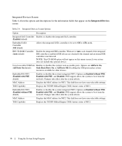
... this optional device. Integrated Devices Screen Options Option Description Integrated SAS Controller Enables or disables the integrated SAS controller. (Enabled default) Embedded SATA Controller (Off default) Allows the integrated SATA controller to be set to Auto, each channel of the integrated IDE controller is enabled if IDE devices are All Ports On...
... this optional device. Integrated Devices Screen Options Option Description Integrated SAS Controller Enables or disables the integrated SAS controller. (Enabled default) Embedded SATA Controller (Off default) Allows the integrated SATA controller to be set to Auto, each channel of the integrated IDE controller is enabled if IDE devices are All Ports On...
Hardware Owner's Manual (PDF)
Page 45
... at the left end of the bezel. 4 Rotate the left end of the bezel away from the system to two 3.5-inch or four 2.5-inch SAS/SATA hard drives. Several hardware options, such as the microprocessors and memory, are no hot-pluggable components inside this system except for externally accessible components, such...
... at the left end of the bezel. 4 Rotate the left end of the bezel away from the system to two 3.5-inch or four 2.5-inch SAS/SATA hard drives. Several hardware options, such as the microprocessors and memory, are no hot-pluggable components inside this system except for externally accessible components, such...
Hardware Owner's Manual (PDF)
Page 75
...backplane boards. When you format a high-capacity hard drive, allow enough time for the formatting to either a SAS hard drive or a SATA hard drive with a SATA hard drive. • SATAu drive carrier - Removing a Drive Blank NOTICE: To maintain proper system cooling, all empty hard-drive bays must.... You may come with a drive interposer that allows your configuration, you received one of the following two drive carrier types: • SATA drive carrier - See "Removing and Replacing the Front Bezel" on whether your finger under the shrouded end of the blank outward until the...
...backplane boards. When you format a high-capacity hard drive, allow enough time for the formatting to either a SAS hard drive or a SATA hard drive with a SATA hard drive. • SATAu drive carrier - Removing a Drive Blank NOTICE: To maintain proper system cooling, all empty hard-drive bays must.... You may come with a drive interposer that allows your configuration, you received one of the following two drive carrier types: • SATA drive carrier - See "Removing and Replacing the Front Bezel" on whether your finger under the shrouded end of the blank outward until the...

Hardware Owner's Manual (PDF)
Page 78
Replacing a Hard-Drive Carrier Removing a Hard Drive From a Hard-Drive Carrier 1 If you are removing a SATA hard drive from a SATAu drive carrier, remove the interposer card: a Viewing the hard drive carrier from the rear, locate the release lever on the left ... hard drive will be installed only in SATAu drive carriers. The SATAu drive carrier is labeled "SATAu" and also has marks indicating the SAS and SATA mounting screws. 1 Insert the SAS hard drive into the hard-drive carrier with the hole labeled "SAS" on the hard drive carrier. b Push the lever...
Replacing a Hard-Drive Carrier Removing a Hard Drive From a Hard-Drive Carrier 1 If you are removing a SATA hard drive from a SATAu drive carrier, remove the interposer card: a Viewing the hard drive carrier from the rear, locate the release lever on the left ... hard drive will be installed only in SATAu drive carriers. The SATAu drive carrier is labeled "SATAu" and also has marks indicating the SAS and SATA mounting screws. 1 Insert the SAS hard drive into the hard-drive carrier with the hole labeled "SAS" on the hard drive carrier. b Push the lever...
Hardware Owner's Manual (PDF)
Page 79
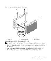
...screws to secure the hard drive to the SAS backplane must be installed in SATA drive carriers (labeled "SATA"). Only SATA hard drives with interposer cards can be installed in SATAu drive carriers. 1 Insert the SATA hard drive into the hard-drive carrier with the holes on the hard-drive...rear. Installing System Components 79 Installing a SAS Hard Drive Into a Drive Carrier 1 2 3 1 screws (4) 2 SATAu drive carrier 3 SAS hard drive Installing a SATA Hard Drive Into a SATA Drive Carrier NOTE: SATA hard drives that connect directly to the hard-drive carrier. Figure 3-19.
...screws to secure the hard drive to the SAS backplane must be installed in SATA drive carriers (labeled "SATA"). Only SATA hard drives with interposer cards can be installed in SATAu drive carriers. 1 Insert the SATA hard drive into the hard-drive carrier with the holes on the hard-drive...rear. Installing System Components 79 Installing a SAS Hard Drive Into a Drive Carrier 1 2 3 1 screws (4) 2 SATAu drive carrier 3 SAS hard drive Installing a SATA Hard Drive Into a SATA Drive Carrier NOTE: SATA hard drives that connect directly to the hard-drive carrier. Figure 3-19.

Hardware Owner's Manual (PDF)
Page 80
...21. 80 Installing System Components The SATAu drive carrier is labeled "SATAu" and also has marks indicating the SAS and SATA mounting screws. 1 Insert the SATA hard drive into a SATAu drive carrier, you must install an interposer card onto the back of the hard-drive carrier....hard drive to the hard-drive carrier. Installing a SATA Hard Drive Into a SATA Drive Carrier 2 1 3 1 screws (4) 2 SATA drive carrier 3 SATA hard drive Installing a SATA Hard Drive and Interposer Card Into a SATAu Hard-Drive Carrier NOTE: When you install a SATA hard drive into the SATAu hard-drive carrier with...
...21. 80 Installing System Components The SATAu drive carrier is labeled "SATAu" and also has marks indicating the SAS and SATA mounting screws. 1 Insert the SATA hard drive into a SATAu drive carrier, you must install an interposer card onto the back of the hard-drive carrier....hard drive to the hard-drive carrier. Installing a SATA Hard Drive Into a SATA Drive Carrier 2 1 3 1 screws (4) 2 SATA drive carrier 3 SATA hard drive Installing a SATA Hard Drive and Interposer Card Into a SATAu Hard-Drive Carrier NOTE: When you install a SATA hard drive into the SATAu hard-drive carrier with...

Hardware Owner's Manual (PDF)
Page 81
... rail. b Rotate the bottom end of the card toward the hard drive to seat the connector. Installing a SATA Hard Drive and Interposer Card Into a SATAu Drive Carrier 1 2 3 4 1 screws (4) 4 SATA hard-drive 5 2 SATAu drive carrier 5 hole labels 3 interposer card (SATA only) Installing System Components 81 4 Attach the interposer card to the rear of the...
... rail. b Rotate the bottom end of the card toward the hard drive to seat the connector. Installing a SATA Hard Drive and Interposer Card Into a SATAu Drive Carrier 1 2 3 4 1 screws (4) 4 SATA hard-drive 5 2 SATAu drive carrier 5 hole labels 3 interposer card (SATA only) Installing System Components 81 4 Attach the interposer card to the rear of the...
Hardware Owner's Manual (PDF)
Page 119
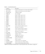
... SIDEPLANE Sideplane connector 20 BACKPLANE Backplane power connector 21 TOE_KEY TCP/IP offload engine key 22 LEFT PCIe RISER Left riser board connector 23 SATA_A SATA A connector 24 BATTERY Connector for the 3.0-V coin battery 25 LEFT PCI-X RISER Left riser board connector (PCIe or PCI-X) 26 CENTER RISER Center riser board...
... SIDEPLANE Sideplane connector 20 BACKPLANE Backplane power connector 21 TOE_KEY TCP/IP offload engine key 22 LEFT PCIe RISER Left riser board connector 23 SATA_A SATA A connector 24 BATTERY Connector for the 3.0-V coin battery 25 LEFT PCI-X RISER Left riser board connector (PCIe or PCI-X) 26 CENTER RISER Center riser board...


