
Microprocessor Installation Information
Page 1
...Install the processor. See "Installing System Components" in the Hardware Owner's Manual included on processor availability and upgrade options for property damage, personal injury, or death. Dell Inc. See www.dell.com and support.dell.com for information on the CDs provided with a "II," your system...CAUTION: A CAUTION indicates a potential for your system. See "Using the System Setup Program" in the Hardware Owner's Manual included on support.dell.com. 3 Download and flash the latest BIOS version if necessary. 4 Check your system BMC firmware version in your system...
...Install the processor. See "Installing System Components" in the Hardware Owner's Manual included on processor availability and upgrade options for property damage, personal injury, or death. Dell Inc. See www.dell.com and support.dell.com for information on the CDs provided with a "II," your system...CAUTION: A CAUTION indicates a potential for your system. See "Using the System Setup Program" in the Hardware Owner's Manual included on support.dell.com. 3 Download and flash the latest BIOS version if necessary. 4 Check your system BMC firmware version in your system...

Installing a SATA Optical Drive
Page 3
...being replaced by a SATA optical drive. See "Removing the Bezel" in your Hardware Owner's Manual. 4 PowerEdge 1950 systems only: Disconnect and remove the SAS controller daughter card. See your Hardware Owner's Manual for specific step instructions. b Remove the center fans and the center fan bracket. See "... back of the tray and slide the drive tray out of the system. Installing a SATA Optical Drive These instructions apply to Dell™ PowerEdge™ systems to remove the system cover and access any of the components inside the system. Removing an Existing Optical Drive -...
...being replaced by a SATA optical drive. See "Removing the Bezel" in your Hardware Owner's Manual. 4 PowerEdge 1950 systems only: Disconnect and remove the SAS controller daughter card. See your Hardware Owner's Manual for specific step instructions. b Remove the center fans and the center fan bracket. See "... back of the tray and slide the drive tray out of the system. Installing a SATA Optical Drive These instructions apply to Dell™ PowerEdge™ systems to remove the system cover and access any of the components inside the system. Removing an Existing Optical Drive -...

Installing a SATA Optical Drive
Page 7
... SATA Optical Drive 7 See "SAS Controller Daughter Card" in your Hardware Owner's Manual. 6 Close the system. See "Closing the System" in your Hardware Owner's Manual. 7 Reconnect the system to the power supply connector. PowerEdge 2970 or 2950 1 Insert the optical drive tray into the system until it is... 6 optical drive 5 Reinstall the SAS controller daughter card and reconnect the SAS cable. Figure 1-3. SATA Cable Routing in the PowerEdge 1950 2 1 3 4 6 5 1 SATA data cable 3 chipset shroud 5 SATA power cable 2 SATA_A connector on the system and attached peripherals.
... SATA Optical Drive 7 See "SAS Controller Daughter Card" in your Hardware Owner's Manual. 6 Close the system. See "Closing the System" in your Hardware Owner's Manual. 7 Reconnect the system to the power supply connector. PowerEdge 2970 or 2950 1 Insert the optical drive tray into the system until it is... 6 optical drive 5 Reinstall the SAS controller daughter card and reconnect the SAS cable. Figure 1-3. SATA Cable Routing in the PowerEdge 1950 2 1 3 4 6 5 1 SATA data cable 3 chipset shroud 5 SATA power cable 2 SATA_A connector on the system and attached peripherals.

Installing a SATA Optical Drive
Page 8
... Owner's Manual. 5 Remove the cable retention bracket from the right interior wall of the chassis by pushing the blue release latch and sliding the bracket toward the front of the system until the bracket detaches from the chassis slots. 6 Route the SATA cable in the cable channel in the PowerEdge 2950 and...
... Owner's Manual. 5 Remove the cable retention bracket from the right interior wall of the chassis by pushing the blue release latch and sliding the bracket toward the front of the system until the bracket detaches from the chassis slots. 6 Route the SATA cable in the cable channel in the PowerEdge 2950 and...

Installing a SATA Optical Drive
Page 9
...an available power supply cable. 5 Replace the center fan bracket. 9 Replace the cooling shroud. For a PowerEdge 2900, use the SATA_D connector. For a PowerEdge 1900, use the SATA_B connector. - PowerEdge 2900 and 1900 1 If the mounting screws are not attached to the drive, install them now. 2 Align...of the fan bracket and connect the cable to the power supply as follows: - See "Replacing the Center Fan Bracket" in your Hardware Owner's Manual. 11 Reconnect the system to power and turn on the system board. See Figure 1-5. - Installing a SATA Optical Drive 9 See Figure 1-5. ...
...an available power supply cable. 5 Replace the center fan bracket. 9 Replace the cooling shroud. For a PowerEdge 2900, use the SATA_D connector. For a PowerEdge 1900, use the SATA_B connector. - PowerEdge 2900 and 1900 1 If the mounting screws are not attached to the drive, install them now. 2 Align...of the fan bracket and connect the cable to the power supply as follows: - See "Replacing the Center Fan Bracket" in your Hardware Owner's Manual. 11 Reconnect the system to power and turn on the system board. See Figure 1-5. - Installing a SATA Optical Drive 9 See Figure 1-5. ...

Installing a SATA Optical Drive
Page 10
Figure 1-5. See "Closing the System" in a PowerEdge 2900 or 1900 3 2 4 5 1 1 optical drive 3 SATA data cable 5 SATA power connector on SAS backplane (PowerEdge 2900 only) 2 SATA power cable 4 SATA connector on system board 8 Reconnect the cables to power and turn on the system and attached peripherals. 10 Installing a SATA Optical Drive SATA Cable Routing in your Hardware Owner's Manual. 10 Reconnect the system to the SAS controller daughter card. 9 Close the system.
Figure 1-5. See "Closing the System" in a PowerEdge 2900 or 1900 3 2 4 5 1 1 optical drive 3 SATA data cable 5 SATA power connector on SAS backplane (PowerEdge 2900 only) 2 SATA power cable 4 SATA connector on system board 8 Reconnect the cables to power and turn on the system and attached peripherals. 10 Installing a SATA Optical Drive SATA Cable Routing in your Hardware Owner's Manual. 10 Reconnect the system to the SAS controller daughter card. 9 Close the system.
Trusted Platform Module (TPM) Update
Page 1
...disclaims any TPM options listed in the "Using the System Setup Program" chapter of Dell Inc. Other trademarks and trade names may be used in this text: Dell and the DELL logo are not equipped with TPM. November 2007 Disregard any proprietary interest in this document... is strictly forbidden. Dell Inc. All rights reserved. Information in this document to refer to change without the written permission of your Hardware Owner's Manual. Trusted Platform Module (TPM) Update Systems that are shipping in China...
...disclaims any TPM options listed in the "Using the System Setup Program" chapter of Dell Inc. Other trademarks and trade names may be used in this text: Dell and the DELL logo are not equipped with TPM. November 2007 Disregard any proprietary interest in this document... is strictly forbidden. Dell Inc. All rights reserved. Information in this document to refer to change without the written permission of your Hardware Owner's Manual. Trusted Platform Module (TPM) Update Systems that are shipping in China...
Information Update
Page 4
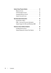
System Setup Program Update 21 Memory Screen 21 CPU Information Screen 22 Integrated Devices Screen 22 System Security Screen 23 Operating System Information 25 Enumeration of NICs 25 RHEL - Incorrect Processor Information 25 System Support for Microsoft Windows 2000 . . . 25 Hardware Owner's Manual Updates 26 Installing the Processor 26 System Diagnostics Custom Test Options . . . . . 26 4 Contents
System Setup Program Update 21 Memory Screen 21 CPU Information Screen 22 Integrated Devices Screen 22 System Security Screen 23 Operating System Information 25 Enumeration of NICs 25 RHEL - Incorrect Processor Information 25 System Support for Microsoft Windows 2000 . . . 25 Hardware Owner's Manual Updates 26 Installing the Processor 26 System Diagnostics Custom Test Options . . . . . 26 4 Contents
Information Update
Page 7
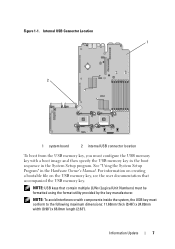
.... Information Update 7 Figure 1-1. NOTE: To avoid interference with a boot image and then specify the USB memory key in the boot sequence in the Hardware Owner's Manual. For information on creating a bootable file on the USB memory key, see the user documentation that contain multiple LUNs (Logical Unit Numbers) must conform to...
.... Information Update 7 Figure 1-1. NOTE: To avoid interference with a boot image and then specify the USB memory key in the boot sequence in the Hardware Owner's Manual. For information on creating a bootable file on the USB memory key, see the user documentation that contain multiple LUNs (Logical Unit Numbers) must conform to...
Information Update
Page 8
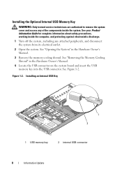
...discharge. 1 Turn off the system, including any of the components inside the system. See "Removing the Memory Cooling Shroud" in the Hardware Owner's Manual. 3 Remove the memory cooling shroud. Installing an Internal USB Key 1 2 1 USB memory key 2 internal USB connector 8 Information Update See "...Opening the System" in the Hardware Owner's Manual. 4 Locate the USB connector on the system board and insert the USB memory key into the USB connector. Installing the Optional Internal USB ...
...discharge. 1 Turn off the system, including any of the components inside the system. See "Removing the Memory Cooling Shroud" in the Hardware Owner's Manual. 3 Remove the memory cooling shroud. Installing an Internal USB Key 1 2 1 USB memory key 2 internal USB connector 8 Information Update See "...Opening the System" in the Hardware Owner's Manual. 4 Locate the USB connector on the system board and insert the USB memory key into the USB connector. Installing the Optional Internal USB ...
Information Update
Page 9
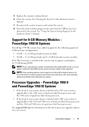
Information Update 9 Support for your system. See support.dell.com for information on the latest processor upgrade options for 8-GB Memory Modules - PowerEdge 1950 III Systems PowerEdge 1950 III systems have added support for the following approved 8-GB memory configurations: • 64 GB - 8 x 8-GB quad-...system only recognizes and displays 63.75 GB during POST. PowerEdge 1950 II and PowerEdge 1950 III Systems • If the front of physical memory. Processor Upgrades - See "Closing the System" in the Hardware Owner's Manual. NOTE: Prior to power and restart the system. 8...
Information Update 9 Support for your system. See support.dell.com for information on the latest processor upgrade options for 8-GB Memory Modules - PowerEdge 1950 III Systems PowerEdge 1950 III systems have added support for the following approved 8-GB memory configurations: • 64 GB - 8 x 8-GB quad-...system only recognizes and displays 63.75 GB during POST. PowerEdge 1950 II and PowerEdge 1950 III Systems • If the front of physical memory. Processor Upgrades - See "Closing the System" in the Hardware Owner's Manual. NOTE: Prior to power and restart the system. 8...
Information Update
Page 11
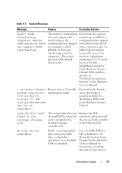
... interleaving. If the problem persists, see "General functionality. controller slot. Invalid PCIe card found in the Hardware Owner's Manual. See "Installing a RAC Card" in the Internal_Storage slot! The system memory configuration runs but with reduced information, see... "Troubleshooting System Memory" in the Hardware Owner's Manual. !!*** Error: Remote Access Controller initialization failure *** RAC virtual USB devices may not be for information on setting the...
... interleaving. If the problem persists, see "General functionality. controller slot. Invalid PCIe card found in the Hardware Owner's Manual. See "Installing a RAC Card" in the Internal_Storage slot! The system memory configuration runs but with reduced information, see... "Troubleshooting System Memory" in the Hardware Owner's Manual. !!*** Error: Remote Access Controller initialization failure *** RAC virtual USB devices may not be for information on setting the...
Information Update
Page 12
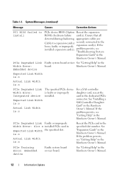
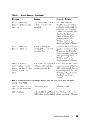
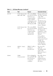
...n Actual Link Width is n The specified PCIe device is n Reseat the PCIe card in the Hardware Owner's Manual. See "Installing a SAS Controller Daughter Card" in the Hardware Owner's Manual. PCIe Degraded Link Faulty or improperly Width Error: Slot n installed PCIe card in the Width Error: board. System...See "Getting Help" in Expected Link Width the specified slot. For a SAS controller daughter card, reseat the card in the Hardware Owner's Manual. If the problem persists, see "Getting Help" in the specified slot number. If the problem persists, see "Getting Help" in the dedicated ...
...n Actual Link Width is n The specified PCIe device is n Reseat the PCIe card in the Hardware Owner's Manual. See "Installing a SAS Controller Daughter Card" in the Hardware Owner's Manual. PCIe Degraded Link Faulty or improperly Width Error: Slot n installed PCIe card in the Width Error: board. System...See "Getting Help" in Expected Link Width the specified slot. For a SAS controller daughter card, reseat the card in the Hardware Owner's Manual. If the problem persists, see "Getting Help" in the specified slot number. If the problem persists, see "Getting Help" in the dedicated ...
Information Update
Page 13
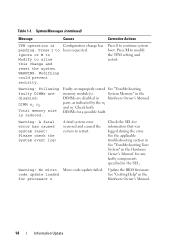
...has failed. See "Expansion Cards" in are connected, and that the RAC cables or RAC card installed in the Hardware Owner's Manual. RAC cables not connected, Check that the wrong expansion slot. TPM configuration System now resets. System Messages (continued) Message Causes Corrective... Actions PCIe Training Error: Integrated device The specified PCIe device is installed in the RAC slot. operation honored. Hardware Owner's Manual. RAC card is faulty or improperly installed. NOTE: All TPM information messages appear after the BMC option ROM has been loaded...
...has failed. See "Expansion Cards" in are connected, and that the RAC cables or RAC card installed in the Hardware Owner's Manual. RAC cables not connected, Check that the wrong expansion slot. TPM configuration System now resets. System Messages (continued) Message Causes Corrective... Actions PCIe Training Error: Integrated device The specified PCIe device is installed in the RAC slot. operation honored. Hardware Owner's Manual. RAC card is faulty or improperly installed. NOTE: All TPM information messages appear after the BMC option ROM has been loaded...
Information Update
Page 14
...and reset the system. pairs, as indicated by the n1 and n2. code update loaded See "Getting Help" in Hardware Owner's Manual. A fatal system error occurred and caused the system to modify the TPM setting and restart. System Messages (continued) Message Causes Corrective... system boot. Warning: Following faulty DIMMs are disabled in the for any faulty components specified in the Hardware Owner's Manual. for processor n Hardware Owner's Manual. 14 Information Update No micro Micro code update failed. Press M to restart. Check both DIMMs for information that ...
...and reset the system. pairs, as indicated by the n1 and n2. code update loaded See "Getting Help" in Hardware Owner's Manual. A fatal system error occurred and caused the system to modify the TPM setting and restart. System Messages (continued) Message Causes Corrective... system boot. Warning: Following faulty DIMMs are disabled in the for any faulty components specified in the Hardware Owner's Manual. for processor n Hardware Owner's Manual. 14 Information Update No micro Micro code update failed. Press M to restart. Check both DIMMs for information that ...
Information Update
Page 15
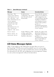
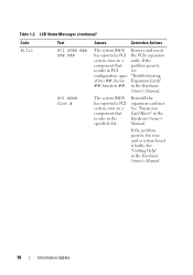
...valid configuration. Write fault Write fault on the PowerEdge 1950 III system and the probable cause for each message. For information on the SEL and configuring system management settings, see "Troubleshooting System Memory" in the Hardware Owner's Manual. If the problem persists, see your systems...installed memory configuration is not optimal. LCD Status Messages Update Table 1-2 lists updates to events recorded in the Hardware Owner's Manual. Information Update 15 Reseat the USB device or USB cable. For hard drive problems, see the system documentation on valid memory...
...valid configuration. Write fault Write fault on the PowerEdge 1950 III system and the probable cause for each message. For information on the SEL and configuring system management settings, see "Troubleshooting System Memory" in the Hardware Owner's Manual. If the problem persists, see your systems...installed memory configuration is not optimal. LCD Status Messages Update Table 1-2 lists updates to events recorded in the Hardware Owner's Manual. Information Update 15 Reseat the USB device or USB cable. For hard drive problems, see the system documentation on valid memory...
Information Update
Page 16
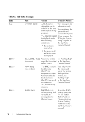
... NAME A 62-character This message is displayed under "Using the System the following Setup Program" in the Hardware to maximum Owner's Manual. defined by the user You can be information only. name in the System Setup system ID and program. Owner... program. "Troubleshooting System Cooling Problems" in the Hardware failure events. See is for critical in the Hardware Owner's Manual. 16 Information Update CPU Temp Interface The BMC is Owner's Manual. as a precautionary measure. or unable to See the "RAID recharge due to determine the system and the CPU(s)...
... NAME A 62-character This message is displayed under "Using the System the following Setup Program" in the Hardware to maximum Owner's Manual. defined by the user You can be information only. name in the System Setup system ID and program. Owner... program. "Troubleshooting System Cooling Problems" in the Hardware failure events. See is for critical in the Hardware Owner's Manual. 16 Information Update CPU Temp Interface The BMC is Owner's Manual. as a precautionary measure. or unable to See the "RAID recharge due to determine the system and the CPU(s)...
Information Update
Page 17
...component that problem persists, resides in the Hardware Owner's Manual. If the problem persists, the riser card or system board is out Check the AC of acceptable range. power source. in the Hardware Owner's Manual. Information Update 17 See "Expansion Card Risers" in... the Hardware Owner's Manual. Reinstall the expansion-card riser. See "Getting Help" in PCI see configuration space "Troubleshooting at...
...component that problem persists, resides in the Hardware Owner's Manual. If the problem persists, the riser card or system board is out Check the AC of acceptable range. power source. in the Hardware Owner's Manual. Information Update 17 See "Expansion Card Risers" in... the Hardware Owner's Manual. Reinstall the expansion-card riser. See "Getting Help" in PCI see configuration space "Troubleshooting at...
Information Update
Page 18
... a PCI system error on a cards. Reinstall the expansion-card riser. See "Getting Help" in the Hardware Owner's Manual. in the Hardware Owner's Manual. 18 Information Update If the problem persists, the riser card or system board is faulty. LCD Status Messages (continued) Code...Remove and reseat has reported a PCI the PCIe expansion system error on a component that problem persists, resides in the Hardware Owner's Manual. See "Expansion Card Risers" in PCI see configuration space "Troubleshooting at bus ##, device Expansion Cards" ##, function ##. Table 1-2. ...
... a PCI system error on a cards. Reinstall the expansion-card riser. See "Getting Help" in the Hardware Owner's Manual. in the Hardware Owner's Manual. 18 Information Update If the problem persists, the riser card or system board is faulty. LCD Status Messages (continued) Code...Remove and reseat has reported a PCI the PCIe expansion system error on a component that problem persists, resides in the Hardware Owner's Manual. See "Expansion Card Risers" in PCI see configuration space "Troubleshooting at bus ##, device Expansion Cards" ##, function ##. Table 1-2. ...
Information Update
Page 19
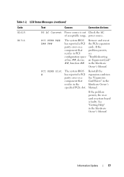
...reported a PCIe fatal error on a component that resides in the specified slot. See "Expansion Card Risers" in the Hardware Owner's Manual. Information Update 19 If the problem persists, the riser card or system board is missing or disconnected. See "Installing a RAC Card"...Reconnect the cable. Reseat the device cable. Remove and reseat the PCIe expansion cards. USB# Overcurrent Device plugged in the Hardware Owner's Manual. If the problem persists, replace or remove the device. If the problem persists, see "Troubleshooting Expansion Cards" in PCIe configuration space ...
...reported a PCIe fatal error on a component that resides in the specified slot. See "Expansion Card Risers" in the Hardware Owner's Manual. Information Update 19 If the problem persists, the riser card or system board is missing or disconnected. See "Installing a RAC Card"...Reconnect the cable. Reseat the device cable. Remove and reseat the PCIe expansion cards. USB# Overcurrent Device plugged in the Hardware Owner's Manual. If the problem persists, replace or remove the device. If the problem persists, see "Troubleshooting Expansion Cards" in PCIe configuration space ...

