Service Manual
Page 3
... 1-5 Hard-Disk Drive Options 1-6 Enhanced Dual-Interface EIDE Subsystem 1-6 Audio Controller 1-6 PCI Video Card 1-6 NIC 1-7 USB 1-7 Desktop Chassis 1-7 Thermal Monitoring 1-7 System Unit 1-8 System Power Supply 1-8 Pin Assignments for the DC Power Connectors 1-8 DC Power Distribution 1-10 System Board Layout 1-12 Video Memory 1-12 Main Memory 1-13 System Board Jumpers 1-13 Interrupt Assignments 1-14...
... 1-5 Hard-Disk Drive Options 1-6 Enhanced Dual-Interface EIDE Subsystem 1-6 Audio Controller 1-6 PCI Video Card 1-6 NIC 1-7 USB 1-7 Desktop Chassis 1-7 Thermal Monitoring 1-7 System Unit 1-8 System Power Supply 1-8 Pin Assignments for the DC Power Connectors 1-8 DC Power Distribution 1-10 System Board Layout 1-12 Video Memory 1-12 Main Memory 1-13 System Board Jumpers 1-13 Interrupt Assignments 1-14...
Service Manual
Page 10
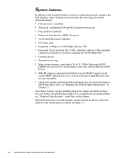
...Dell OptiPlex GXpro Systems Service Manual When following new and/or advanced features: • Dual-processor capability. • Advanced combination ISA and PCI expansion subsystem. • Plug and Play capability. • Enhanced dual-interface EIDE subsystem. • 16-bit integrated audio controller. • PCI video card...more information about Run Quick Tests, see "Technical Specifications" found in a traditional personal computer, the Dell OptiPlex GXpro desktop systems include the following the text in this chapter. System Features In addition to the standard features found ...
...Dell OptiPlex GXpro Systems Service Manual When following new and/or advanced features: • Dual-processor capability. • Advanced combination ISA and PCI expansion subsystem. • Plug and Play capability. • Enhanced dual-interface EIDE subsystem. • 16-bit integrated audio controller. • PCI video card...more information about Run Quick Tests, see "Technical Specifications" found in a traditional personal computer, the Dell OptiPlex GXpro desktop systems include the following the text in this chapter. System Features In addition to the standard features found ...
Service Manual
Page 12
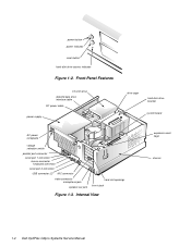
Internal View expansion-card cage chassis 1-4 Dell OptiPlex GXpro Systems Service Manual power button power indicator reset button hard-disk drive access indicator Figure 1-2. Front-Panel Features 3.5-inch drive diskette/tape drive interface cable ... system board AC power receptacle voltage selection switch parallel port connector serial port 1 connector mouse connector keyboard connector serial port 2 connector USB connector (2) NIC connector video connector microphone jack speaker-out jack card-slot openings line-in jack Figure 1-3.
Internal View expansion-card cage chassis 1-4 Dell OptiPlex GXpro Systems Service Manual power button power indicator reset button hard-disk drive access indicator Figure 1-2. Front-Panel Features 3.5-inch drive diskette/tape drive interface cable ... system board AC power receptacle voltage selection switch parallel port connector serial port 1 connector mouse connector keyboard connector serial port 2 connector USB connector (2) NIC connector video connector microphone jack speaker-out jack card-slot openings line-in jack Figure 1-3.
Service Manual
Page 14
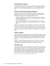
... Labs ViBRA 16 audio controller chip and connectors on the Sound Blaster expansion card from Creative Laboratories, Inc. PCI Video Card The video subsystem consists of which can contain up to two high- NOTE: Some users may use an ISA video adapter card. 1-6 Dell OptiPlex GXpro Systems Service Manual Enhanced Dual-Interface EIDE Subsystem The enhanced dual-interface EIDE...
... Labs ViBRA 16 audio controller chip and connectors on the Sound Blaster expansion card from Creative Laboratories, Inc. PCI Video Card The video subsystem consists of which can contain up to two high- NOTE: Some users may use an ISA video adapter card. 1-6 Dell OptiPlex GXpro Systems Service Manual Enhanced Dual-Interface EIDE Subsystem The enhanced dual-interface EIDE...
Service Manual
Page 20
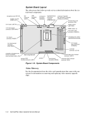
...RSR PWR1) System Board Layout The subsections that came with your system for information on removing and replacing video-memory upgrade chips. 1-12 Dell OptiPlex GXpro Systems Service Manual NIC connector (ENET) USB connector (USB) serial port 2 connector (SERIAL2) keyboard/mouse...MICROPROCESSOR) riser board power connector (RSR PWR2) 3.3-V power input connectors (POWER2) CD-ROM connector (CD_IN) secondary microprocessor card (or terminator card) connector (2ND_CPU) front of system unit primary EIDE interface connector (IDE1) jumpers control panel connector (PANEL) diskette/tape...
...RSR PWR1) System Board Layout The subsections that came with your system for information on removing and replacing video-memory upgrade chips. 1-12 Dell OptiPlex GXpro Systems Service Manual NIC connector (ENET) USB connector (USB) serial port 2 connector (SERIAL2) keyboard/mouse...MICROPROCESSOR) riser board power connector (RSR PWR2) 3.3-V power input connectors (POWER2) CD-ROM connector (CD_IN) secondary microprocessor card (or terminator card) connector (2ND_CPU) front of system unit primary EIDE interface connector (IDE1) jumpers control panel connector (PANEL) diskette/tape...
Service Manual
Page 25
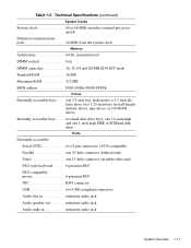
... 3.5-inch bay, dedicated to a 3.5-inch diskette drive; two hard-disk drive bays; Table 1-5. one 15-hole connector (on add-in video card) PS/2-style keyboard . . . . . 6-pin mini-DIN PS/2-compatible mouse 6-pin mini-DIN NIC RJ45 connector USB two USB-compliant connectors Audio line in miniature audio ...
... 3.5-inch bay, dedicated to a 3.5-inch diskette drive; two hard-disk drive bays; Table 1-5. one 15-hole connector (on add-in video card) PS/2-style keyboard . . . . . 6-pin mini-DIN PS/2-compatible mouse 6-pin mini-DIN NIC RJ45 connector USB two USB-compliant connectors Audio line in miniature audio ...
Service Manual
Page 26
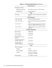
two 40-pin connectors on PCI local bus Diskette drive 34-pin connector Video Video type PCI video card (see manufacturer's specifications) Key Combinations Technical Specifications (continued) Ports (continued) Internally accessible: EIDE hard-disk drive . . . . Table 1-5.
two 40-pin connectors on PCI local bus Diskette drive 34-pin connector Video Video type PCI video card (see manufacturer's specifications) Key Combinations Technical Specifications (continued) Ports (continued) Internally accessible: EIDE hard-disk drive . . . . Table 1-5.
Service Manual
Page 30
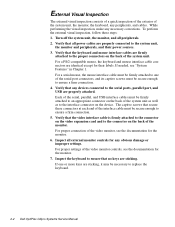
...connected to replace the keyboard. 2-2 Dell OptiPlex GXpro Systems Service Manual Turn off the system unit, the monitor, and all power cables are sticking. Verify that the video interface cable is firmly attached to the connector on the video expansion card and to ensure that all peripherals.... 2. If needed, see the documentation for the monitor. 7. For proper settings of the video monitor, see "System Features" in ...
...connected to replace the keyboard. 2-2 Dell OptiPlex GXpro Systems Service Manual Turn off the system unit, the monitor, and all power cables are sticking. Verify that the video interface cable is firmly attached to the connector on the video expansion card and to ensure that all peripherals.... 2. If needed, see the documentation for the monitor. 7. For proper settings of the video monitor, see "System Features" in ...
Service Manual
Page 36
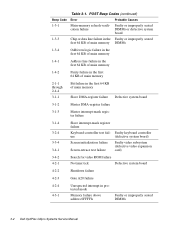
... test failure Faulty keyboard controller (defective system board) Faulty video subsystem (defective video expansion card) 3-4-2 4-2-1 Search for video ROM failure No timer tick Defective system board 4-2-2 Shutdown failure 4-2-3 Gate A20 failure 4-2-4 4-3-1 Unexpected interrupt in protected mode Memory failure above address 0FFFFh Faulty or improperly seated DIMMs 3-2 Dell OptiPlex GXpro Systems Service Manual POST Beep Codes (continued) Beep...
... test failure Faulty keyboard controller (defective system board) Faulty video subsystem (defective video expansion card) 3-4-2 4-2-1 Search for video ROM failure No timer tick Defective system board 4-2-2 Shutdown failure 4-2-3 Gate A20 failure 4-2-4 4-3-1 Unexpected interrupt in protected mode Memory failure above address 0FFFFh Faulty or improperly seated DIMMs 3-2 Dell OptiPlex GXpro Systems Service Manual POST Beep Codes (continued) Beep...
Service Manual
Page 74
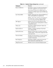
Table A-1. This feature should not be enabled unless an expansion card that can be shadowed or cached. Fast Video BIOS Enables shadowing and caching the BIOS for a video card installed in an expansion slot. Password Status Provides an extra measure of keyboard errors during POST.... rated speed or a slower compatibility speed. Num Lock Determines whether keyboard's Num Lock mode is installed. A-4 Dell OptiPlex GXpro Systems Service Manual NOTE: Some video cards are not designed to System Setup program. Setup Password Restricts access to be supplied by letting you set the ...
Table A-1. This feature should not be enabled unless an expansion card that can be shadowed or cached. Fast Video BIOS Enables shadowing and caching the BIOS for a video card installed in an expansion slot. Password Status Provides an extra measure of keyboard errors during POST.... rated speed or a slower compatibility speed. Num Lock Determines whether keyboard's Num Lock mode is installed. A-4 Dell OptiPlex GXpro Systems Service Manual NOTE: Some video cards are not designed to System Setup program. Setup Password Restricts access to be supplied by letting you set the ...
Service Manual
Page 79
...location on back panel, 1-4 location on system board, 1-12, 4-16 N NIC description, 1-7 location, 1-4, 1-12 Plug and Play expansion cards, 1-5 POST beep codes, 3-1 power button location, 1-4 removal, 4-5 power distribution diagram, 1-11 power indicator, 1-4 power input connectors, 1-..., 4-19 P padlock, 4-4 PANEL connector, 4-16 Panel connector, 1-12 parallel port connector location, 1-4, 1-12, 4-16 PCI expansion cards, 1-5, 1-12, 4-16, 4-17, 4-18 PCI video card, 1-6 S secondary microprocessor, 4-23 serial port connectors, location, 1-4 SMART support, 1-8 sockets battery, 1-12, 4-25 DIMM, 1-12...
...location on back panel, 1-4 location on system board, 1-12, 4-16 N NIC description, 1-7 location, 1-4, 1-12 Plug and Play expansion cards, 1-5 POST beep codes, 3-1 power button location, 1-4 removal, 4-5 power distribution diagram, 1-11 power indicator, 1-4 power input connectors, 1-..., 4-19 P padlock, 4-4 PANEL connector, 4-16 Panel connector, 1-12 parallel port connector location, 1-4, 1-12, 4-16 PCI expansion cards, 1-5, 1-12, 4-16, 4-17, 4-18 PCI video card, 1-6 S secondary microprocessor, 4-23 serial port connectors, location, 1-4 SMART support, 1-8 sockets battery, 1-12, 4-25 DIMM, 1-12...
Service Manual
Page 80
... advanced expansion, 1-5 enhanced dual-interface EIDE, 1-6 main memory, 1-13 video memory, 1-12 switch, voltage selection, 1-4 system board components removal, 4-16...card, removal, 4-23 thermal monitoring, 1-7 troubleshooting boot routine, interpreting, 2-3 external visual inspection, 2-2 initial procedures, 2-1 initial user contact, 2-1 internal visual inspection, 2-4 U USB description, 1-7 location, 1-4, 1-12 user contact, initial, 2-1 V video connector location, 1-4 video subsystem, 1-6 visual inspection external, 2-2 internal, 2-4 voltage selection switch, 1-4 4 Dell OptiPlex GXpro...
... advanced expansion, 1-5 enhanced dual-interface EIDE, 1-6 main memory, 1-13 video memory, 1-12 switch, voltage selection, 1-4 system board components removal, 4-16...card, removal, 4-23 thermal monitoring, 1-7 troubleshooting boot routine, interpreting, 2-3 external visual inspection, 2-2 initial procedures, 2-1 initial user contact, 2-1 internal visual inspection, 2-4 U USB description, 1-7 location, 1-4, 1-12 user contact, initial, 2-1 V video connector location, 1-4 video subsystem, 1-6 visual inspection external, 2-2 internal, 2-4 voltage selection switch, 1-4 4 Dell OptiPlex GXpro...


